
Yes, no problem. I will sent pm youCan you upload the firmware?
Sponsored
Yes, no problem. I will sent pm youCan you upload the firmware?
We need an awards ceremony- this would get GOLD!One of the best posts, yet.
Nicely done! Can't wait to add this to my truck, now knowing it can be done!
Only a Lariat with ACC or a Hybrid will have an electric brake booster. Some have added ACC to an EB without switching to the elctric brake booster but there could be issues with stop and go driving with ACC.not sure if it has already been posted here but; i read initially that the issue with activating this on an ecoboost is the brake booster but I also read that the lariat lux has it. Is that correct? could I go through with this on my lariat?
you really want to be careful doing this, or honestly just not paying full attention at any time when driving with ACC.No possible to hack that, is inside pscm firmware. Keep your hands on steering wheel while driving, lane centering is good to have but it can’t drive by you. But, I watched some video that from a russian guy that holds a 0.5kg piece of something on Ford Fusion steering wheel in someway and it works. I will share
Very elaborate DIY. Only thing is I would never be able to accomplish this task myself. The question I have is will Ford do this for you?Hi gang,
I have successfully retrofitted adaptive cruise control on an XLT Lux Hybrid. This walk-through should work on any trim level Maverick, but there are additional steps required to get this working on an EcoBoost model that will not be documented here.
Requirements
Required parts not listed above:
- Your truck needs to be parked on a level surface. This is to accurately aim/level the CCM once it is attached.
- The following components will be needed. Take note of the WRONG GRILLE PART NUMBER (I ordered NZ6Z-8200-BA, it is the XLT grille).
EDIT 5/3: Fairly confident the grille is NZ6Z-8200-DA and the air deflector is NZ6Z-8312-A
Part Desc Price Per Qty Total W506976-S450B Self-tapping screws $1.50 4 $6.00 NZ6Z-9E731-A Sensor Assembly - Speed $370.61 1 $370.61 NZ6Z-14C022-A Bracket $51.62 1 $51.62 NZ6Z-17E810-AA CCM cover $17.66 1 $17.66 WPT-1198 8-pin pigtail for radar sensor $21.19 1 $21.19 SW8585 Adaptive cruise control steering wheel buttons $56.58 1 $56.58 $636.44 - FORScan
- A test build for 2022 Maverick can be found here: https://forscan.org/download/FORScanSetup2.3.48.test20220425.exe
- If you are new to FORScan, start here: https://www.mavericktruckclub.com/forum/threads/forscan-101-step-by-step-how-to-start-guide.7406/
- Along with FORScan, you'll need an OBD cable for your laptop. I used the FORScan recommended cable linked to on their "products" page. https://forscan.org/download.html
- A moving blanket or other material to protect the bumper cover when you remove it from the car
- Metric sockets (7mm and 10mm) and a T-30 Torx.
- Trim removal tools (plastic pry tools)
- Heat gun
- A torch can be substituted, but it is EXTREMELY easy to ignite heat shrink tubing and solder connectors with an open flame.
- Wire stripper
- Female pin terminals for modifying the IPMA harness connector
- I do not know what part number these should be, but they should be purchased from Ford. I ordered some female Molex pins from Digikey and they fit, but I had to modify them slightly.
- You will not need the entire connector, but one way of obtaining the correct terminals would be to obtain the entire connector with pigtail. The service part number for the IPMA connector is MU2Z-14S411-RA. The pigtail part number is WPT-1686. I have not had success in finding either. I hope you have better luck.
- EDIT 7/22: Terminal pins with pre-crimped wire for the IPMA connector is part number LU2Z-14474-AA. I ordered these and successfully installed them. They include a ferrule if you want to crimp them instead of solder (I recommend soldering) and dual wall heatshrink tubing which has an embedded adhesive that activates when heated. Thanks to @Gilbillygucci for the info.
- Heat shrink solder connectors
- Heat shrink tubing
- Fuse tap
- High-heat-rated automotive harness tape
- Zip ties
- Terminal distribution block or ring crimp terminal
- If you are like me, this is probably one of several electronics additions you will be making to this truck. Installing a distribution block for ground connections will make this and future wiring jobs easier and more robust.
- Alternatively, you can use a single ring crimp terminal for grounding the CCM.
Optional parts missing from the above list:
I purchased a grille with a part number that I thought was for the Lariat Lux, and I was wrong. An XLT grille identical to mine arrived in the mail. I modified it to make it work, but I'd like to go back and get the proper grille later on. Same with the air deflector.
- Grille for Lariat Lux
- EDIT 5/3: After some further research, I am fairly confident that the Lariat Lux grille is part number NZ6Z-8200-DA. Unfortunately, it is backordered from Ford parts, and it is $257.68 retail.
- Air deflector for Lariat Lux
- EDIT 5/3: After some further research, I am fairly confident that the Lariat Lux air deflector is part number NZ6Z-8312-A. $73.72 retail.
- Fish tape or coat hanger (to aide in pulling wires)
High level overview
Install steering wheel switch
- Install steering wheel switch
- Remove bumper cover
- Install vehicle speed sensor
- Pull wiring from speed sensor to fuse block
- Pull wiring from IPMA to fuse block
- Level speed sensor
- Forscan programming and calibration
For ACC to work well and to be able to change the forward vehicle spacing and lane centering, you will need to swap the ACC switch cluster on the steering wheel for your current left-hand buttons.
This post by @Bushpilot includes step-by-step instructions on swapping the steering wheel buttons.
https://www.mavericktruckclub.com/f...scape-steering-wheel.7287/page-23#post-177947
This post by @Tyvemattis details how to remove the steering wheel and swap the buttons.
https://www.mavericktruckclub.com/f...her-switches-such-as-cruise-control-diy.7358/
Bumper cover removal
1. As with any other vehicle modification job, before you start, remove the negative battery lead from the 12v battery beneath the back seat.
2. The factory manual instructs you to jack up the front end and remove both front wheels. This would have made accessing certain components easier, but ultimately was not necessary.
3. Remove forward stone deflectors on driver and passenger sides.
The plastic stone deflectors are fastened with one push pin and 7 machine screws. Use a 7mm socket to remove the screws. Turning the steering wheel helped access these without removing the wheels. If you haven't done so before, removing the push pins requires a thin prying tool to raise the inner pin (see the box labeled 1 below). Then the outer pin can be pried out.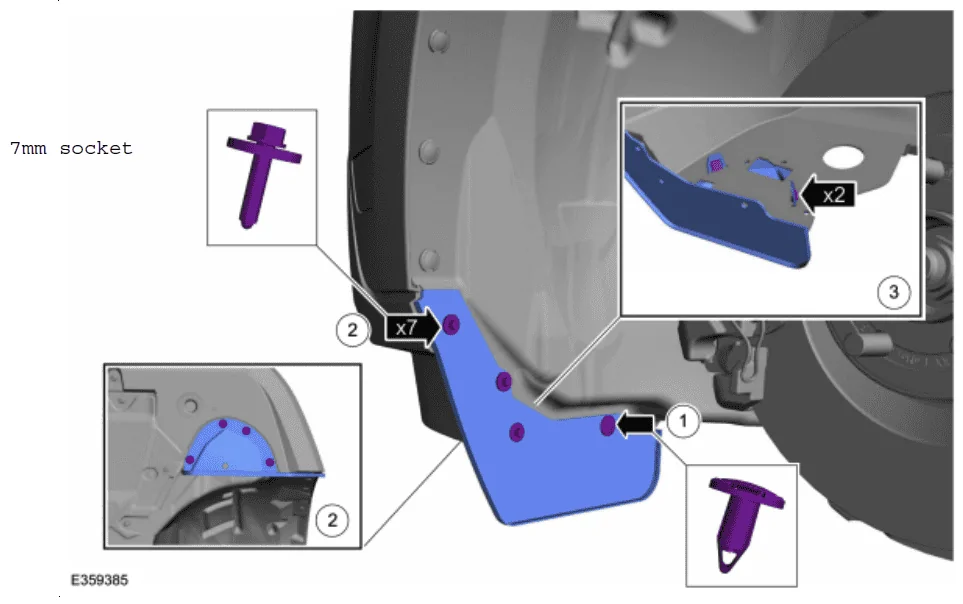
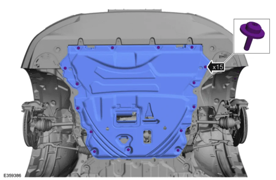
4. Remove the screws and engine undershield. Use a T30 Torx bit.
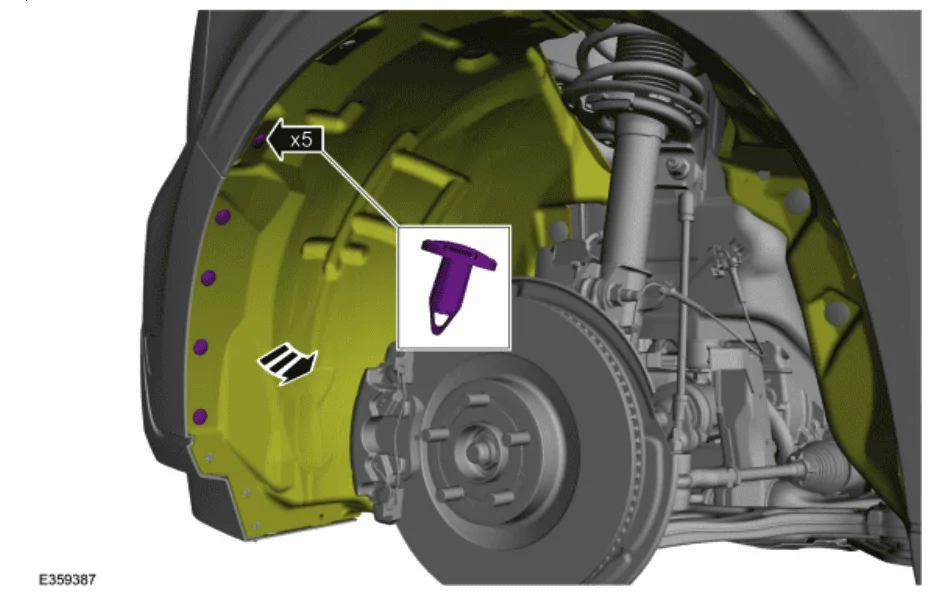
5. Remove the 5 push pins securing the fender liner on both the driver and passenger sides.
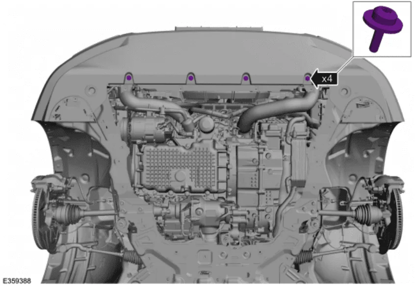
6. Remove the four screws securing the lower bumper cover. Use a T30 Torx.
7. Disconnect the front bumper wiring harness.
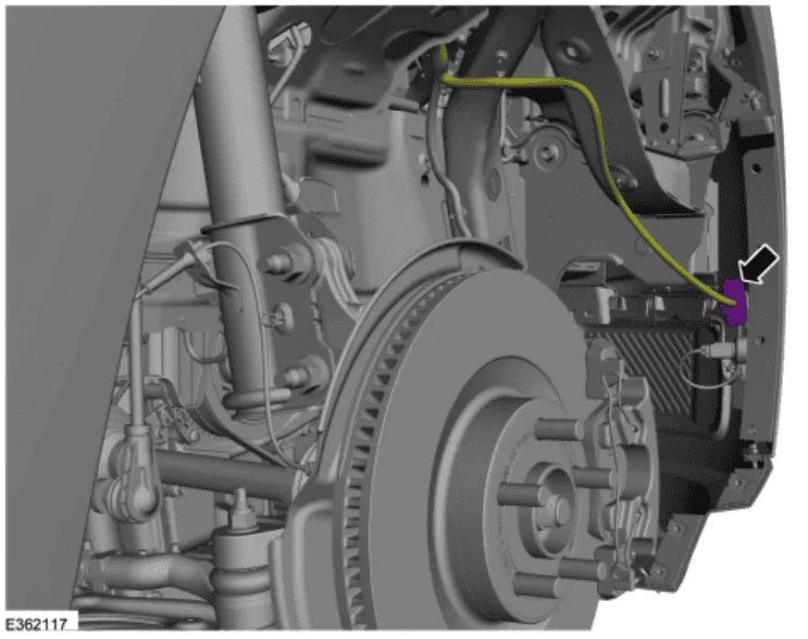
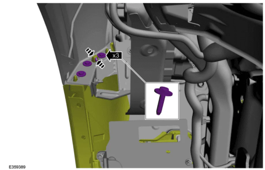
8. On both sides, remove the three bolts securing the front bumper cover to the fender. Release the clips as shown. Use a 10mm socket.
9. At this point, you will want to put a moving blanket on the ground under the front of the vehicle to allow careful easing of the bumper cover to the ground so to avoid paint damage when lowering the bumper cover. The manual suggests having another person help, although I found this unnecessary.
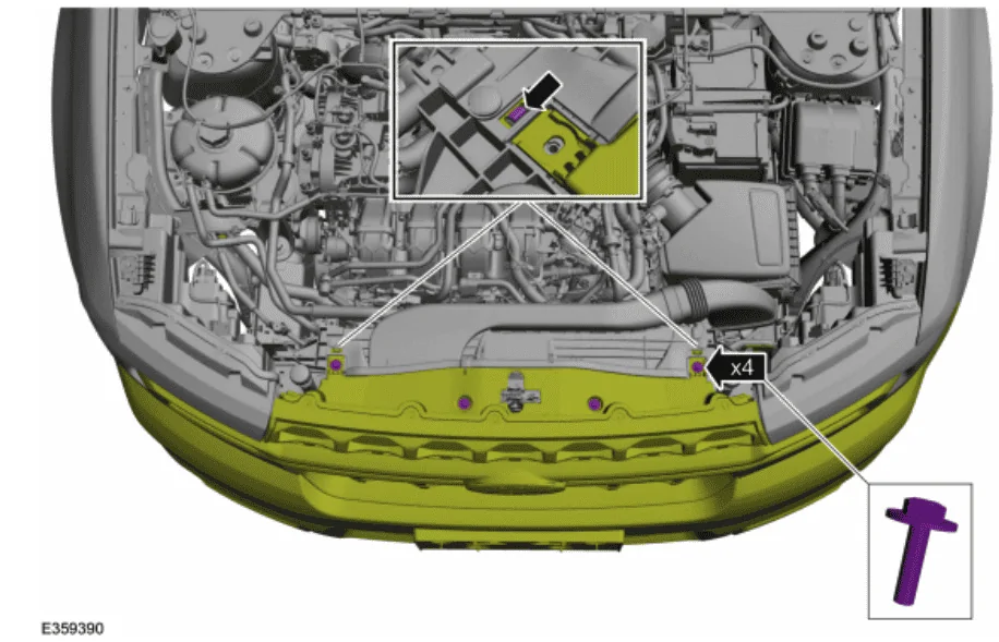
10. Remove the four screws holding the bumper cover to the air intake. Release the two clips as shown below.
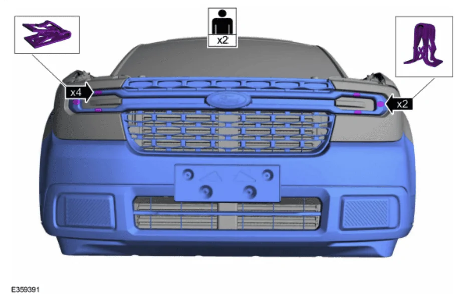
11. Release the three clips behind each headlight trim piece. Best to use a plastic trim removal tool to prevent damage to the headlights.
Your bumper cover should now be on the ground. Congratulations.
If you need additional details, the factory instructions can be found in this PDF: bumper cover removal
Air Deflector Removal
Wiring the CCM
- You now need to remove the stock air deflector. To do this:
- Remove the two hex screws (7mm I think) in red.
- Remove the four push pin fasteners in blue.
- Release the four clips in green. Use a pry tool to gently pull up while gently pulling forward on the air deflector. Each one should allow it to move forward a little more, until you release the last one and the piece will come off entirely.
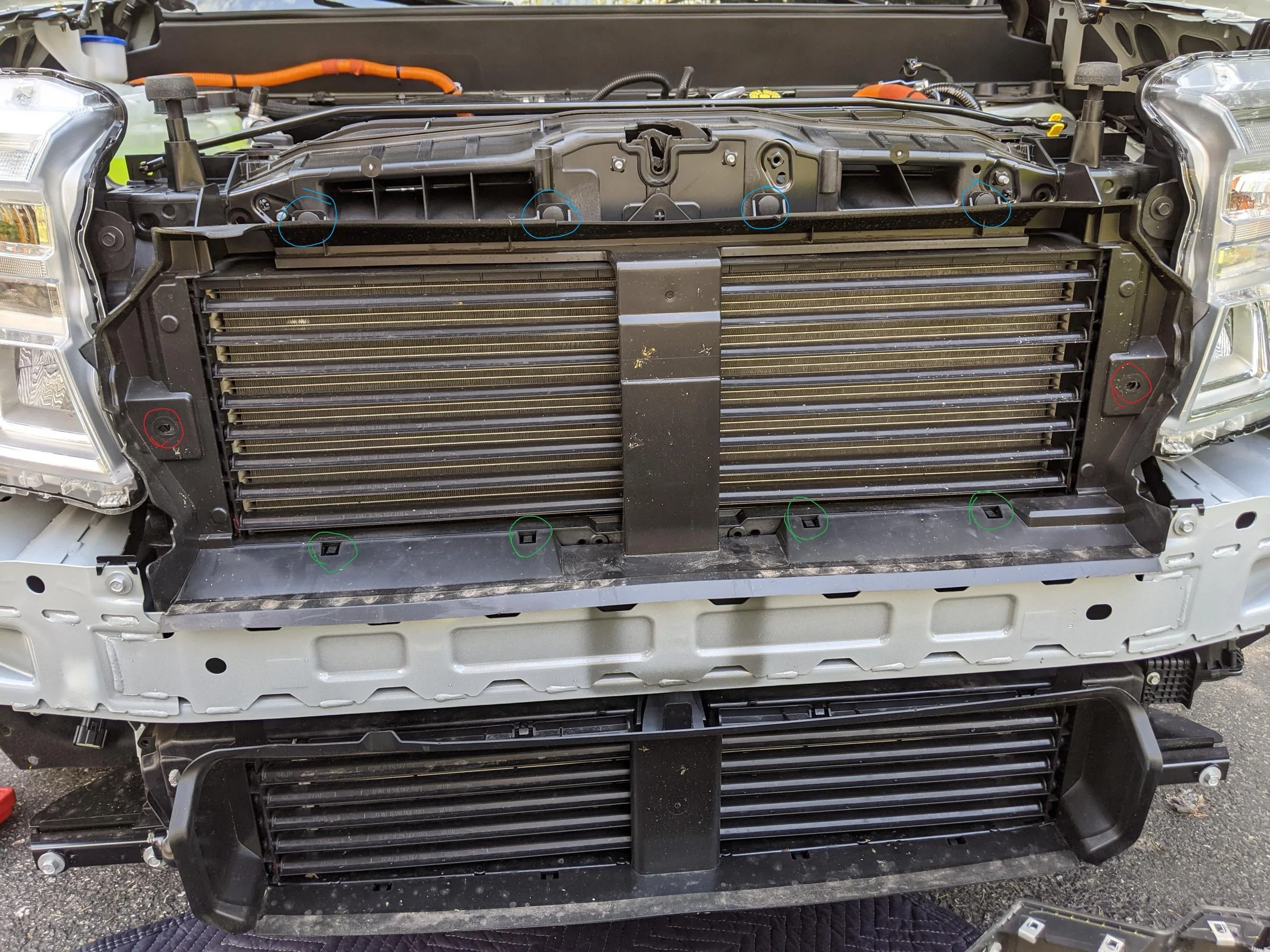
- With the air deflector removed, you will be able to mount the CCM bracket. The CCM bracket attaches using the three holes circled in red below and the self-tapping screws listed in the parts list above.
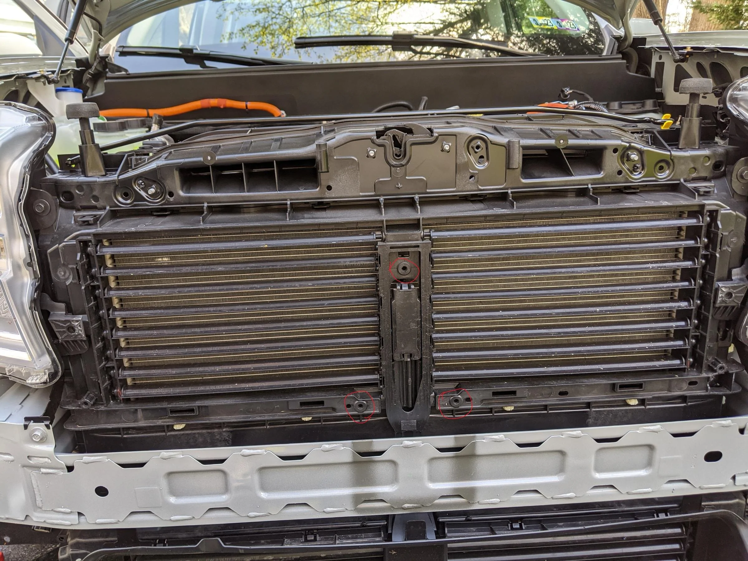
- The speed sensor attaches to the bracket using the three round grommets, pressing onto the three exposed bolts. This required a bit of force. You will hear a satisfying "pop" when it is in place, and it will be firmly attached.
- You now need to level the speed sensor. Using a combination square or some other similar bubble level, ensure the front vertical surface of the speed sensor is level. If it is not, turn the bottom grommet screw with a Torx bit to adjust the angle of the sensor until it is level.
- The factory manual for this process can be found here: CC-M removal/installation
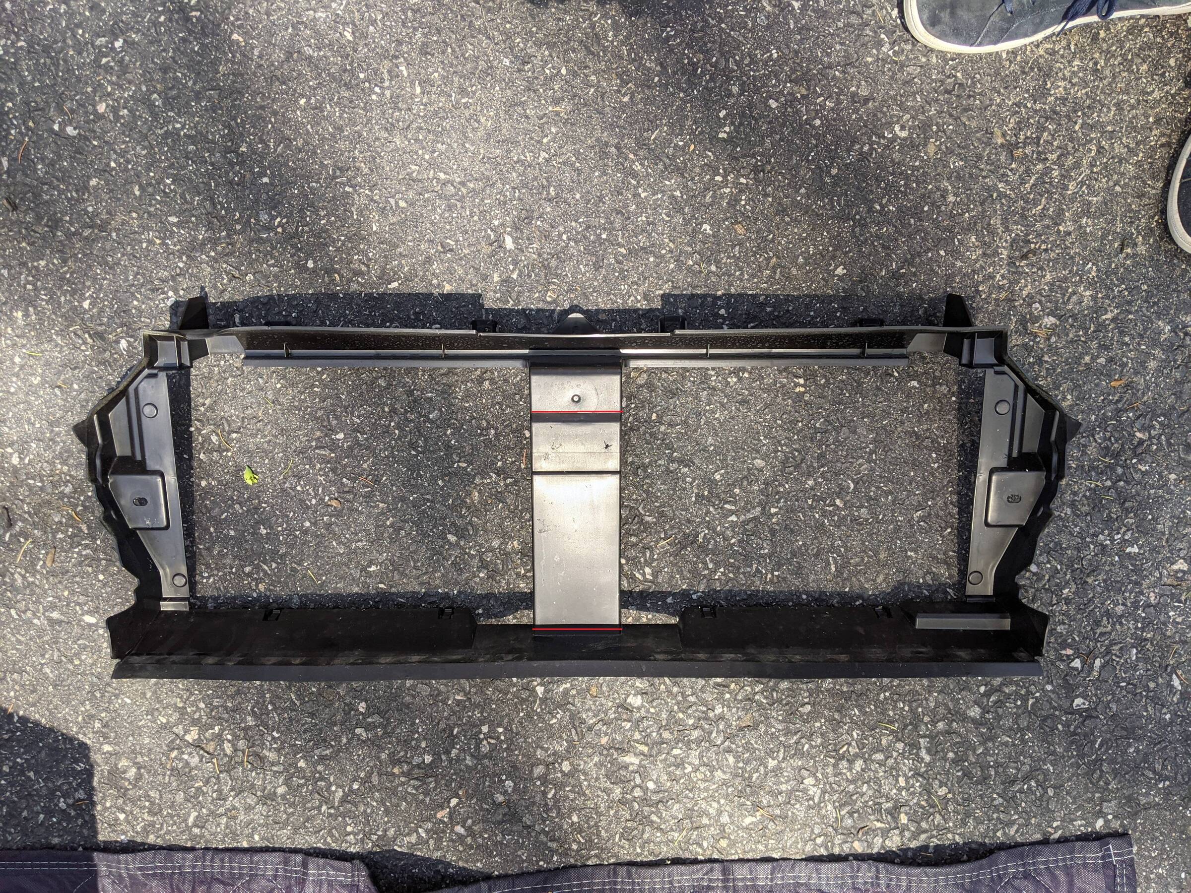
- ** This is where your process may deviate from my own if you obtained the factory grille and air deflector. The steps that follow assume you are keeping the stock XLT air deflector and grille.
- Remove the center section of the XLT air deflector with a hand saw, cutting along the red lines. You may want to determine exactly where to cut by holding your air deflector against where the speed sensor sits on your truck. It will give you greater precision when making these cuts.
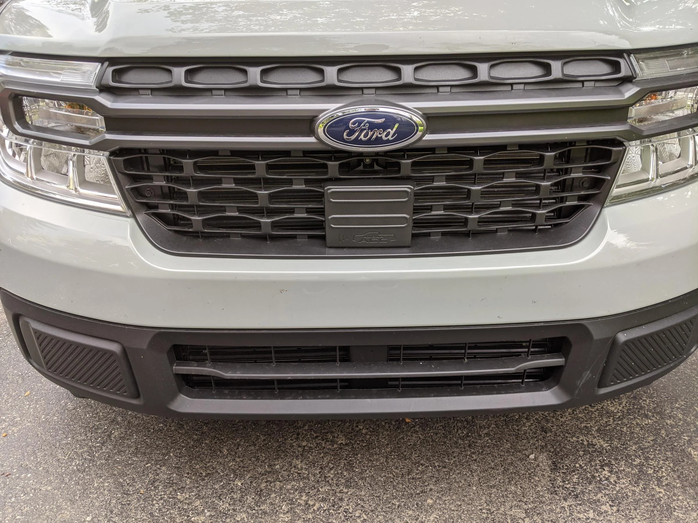
- If you are using the stock XLT grille, line up the CCM cover at the bottom center of the "grid" and mark using a pencil where to cut.
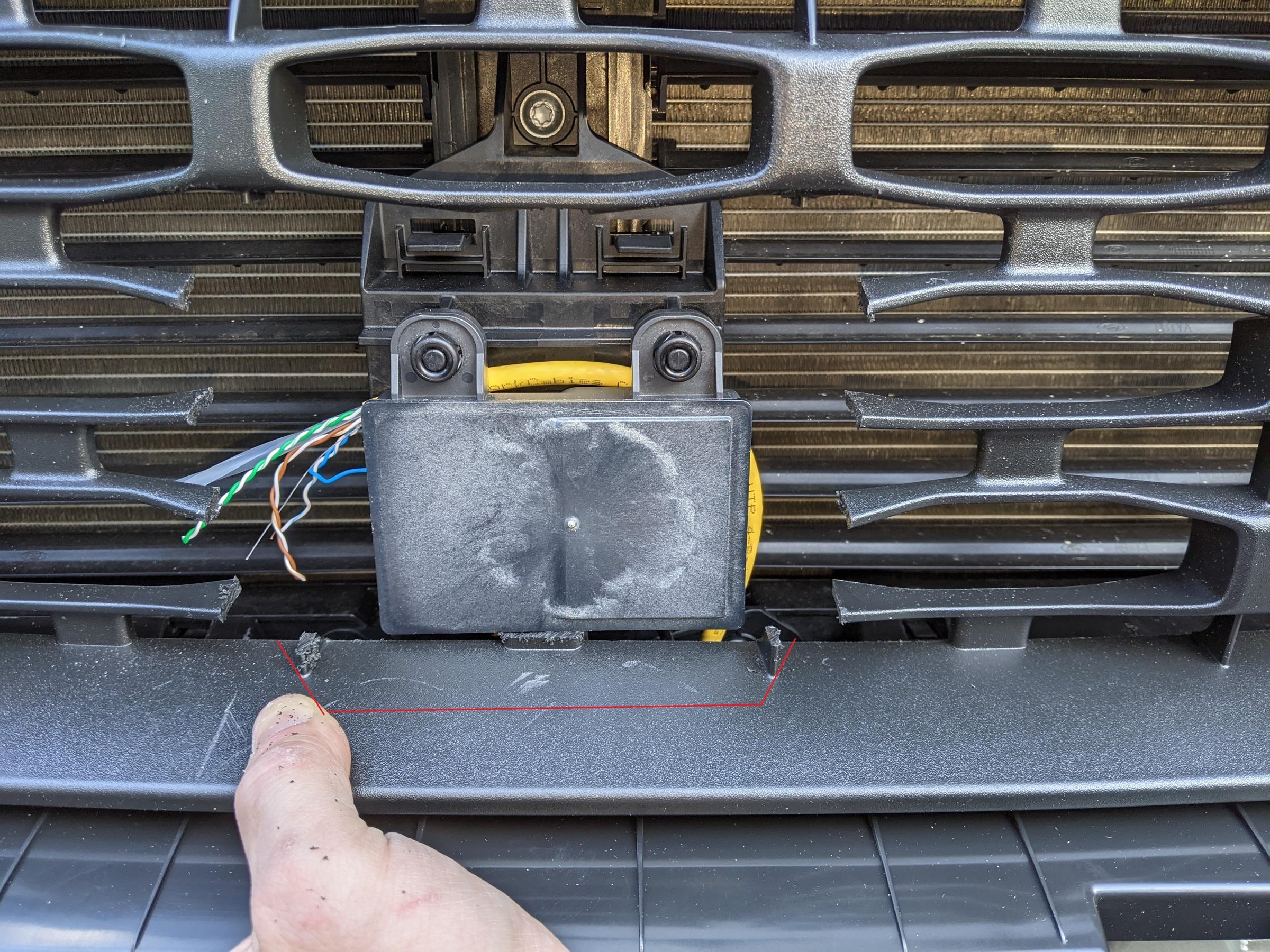
- When I was finished, the CCM cover fits perfectly in the space removed from the XLT grille. It is held in place pretty well without any additional modifications necessary.
I am not going to lie to you, this part was by far the most tedious for me. I am hoping that these instructions serve to make this part simple and straight-forward.
Before we dive into what to do, I want to offer some background on the theory behind what we're doing. In these vehicles, the IPMA (image processing module, located above the rearview mirror) instructs the car how to behave for lane keeping assist, lane centering, pre-collision mitigation, etc. Adding the cruise control module enables lane centering and speed adjustments based on vehicles moving in front using the forward-facing radar sensor (CCM) we just installed.
The CCM communicates directly with the IPMA, which then instructs the rest of the vehicle's modules to do whatever needs to be done including steering, speed adjustments, braking, icons/warnings, etc.
We are running a total of four wires to the CCM. Two of the wires are power and ground. These will terminate in the fuse block located beneath the glove box. The other two wires are CAN bus high and low, by which the CCM sends radar data back to the IPMA. These two wires run directly from the CCM through the firewall, up the passenger side A-pillar, across the headliner, and into the IPMA. When I was first attempting this, I misunderstood the CAN wiring diagram and (mistakenly) thought the CCM sent instructions out over the CAN bus directly. I was wrong, it sends these instructions to the IPMA only.
Here is the CCM wiring diagram for reference: wiring diagram
Unfortunately I do not have pictures for this section right now. Next time I have the trim opened up I will take some photos to add context.
I used riser-rated CAT6 22AWG networking cable for the wiring connections. You may want to obtain Motorcraft-specific wire.
Congratulations, you should now have the CCM harness pulled all the way through from the IPMA and fuse block, through the firewall, and to the CCM. You've earned a break. Have a beer.
- Unclip the passenger trim on the A pillar.
- Use a pry tool at the top of the trim and the top retaining clip will release.
- The bottom of the trim is held down with a retaining clip going vertically into the dash. Once the top is released, pull it away from the pillar and pull the bottom up and out.
- You can then rotate the trim around on the bungee cord it is fastened to and let it hang free in the door jab.
- Remove the glove box.
- There is a black piston on the right-hand side of the box. Pinch together the ends of the retaining post and the piston will slide out.
- There are two tabs, one on each side of the glove box, that must be depressed from the outside of the glove box.
- You can then rotate the glove box down. When it is almost touching the floor, you can lift it forward and out. I put this on the driver side foot well for safe keeping.
- Remove the plastic panel covering the fuse block, just below/behind the glove box. You may need to remove carpets or floor liners to access the panel. The panel just pulls away from the fuse block.
- Use your pry tool to remove the fascia covering the IPMA above the rearview mirror. These retaining clips were tight, I was worried about breaking the piece the entire time.
- Once the retaining clips are released, there is a short (~4") retaining cord holding the fascia to the bracket. The retaining cord has two flat sections rotated 90-degrees from each other. Wiggle the cord around until one flat section is out, then rotate the cord another 90-degrees and the second piece will come out, freeing the cord entirely. The fascia fits in the glove box. I left it there until I was finished so it did not get damaged.
- For this step, you will need two wires. Using a zip tie or electrical tape, secure ~5" of the two wires to the bundle going to the IPMA connector.
- Note which two wires you used, and decide which will be CAN high and which will be CAN low. Write this down somewhere safe. You will need to know later on.
- Working your way out to the right from the IPMA, tuck the two wires up into the space where the headliner meets the windshield.
- Once you reach the A-pillar, route the wires behind the air bag and down the opening at the base of the A-pillar.
- I zip-tied this wire in several places to the other bundles traveling along the A-pillar to keep it from getting pulled out. You could use zip ties, electrical tape, or fabric automotive wiring tape.
- You should be able to find your wires near the fuse block. Put them off to the side for now.
- Grab your fuse tap. Make sure the size you have fits the slots for fuse #3 or #6. These two fuses are key-switched since we only need the CCM powered when the vehicle is running.
- Grab another set of two wires, preferably colored differently from the pair we just used. If you can use black and red, that would be ideal because these two are going to be your power and ground wires.
- Once you've made sure the fuse tap fits, strip the power wire and crimp the wire into the fuse tap.
- Before you start pulling fuses, now would be a really good time to make sure you pulled the negative terminal on the 12v battery.
- Attach the fuse tap to #3 or #6. Make sure to insert both the original fuse in the slot closest to the blades, and the additional fuse for the CCM.
- If you decided to install a ground terminal block, it can be secured somewhere out of the way near the fuse block. You can secure it with machine screws or double-sided adhesive foam tape.
- Secure your ground wire to either the terminal block or ring crimp terminal.
- With all four wires now secured, hold them together and begin wrapping the four wires with harness tape. You will need roughly 10 feet (3m) of this 4-wire harness to reach the CCM in the front grille.
- When finished wrapping, you will need a semi-long sharp implement to pierce the boot where the main wiring harnesses exit the firewall into the engine compartment. You can locate the boot by reaching up and to the right above the fuse block and follow the large harness with your hand. The other side of the harness can be seen from the engine compartment to the rear of the engine coolant reservoir. Take care to pierce the boot on the side to avoid damaging any of the other harness wires.
- Feed your new CCM harness through the hole you just made, and pull the slack through to the engine compartment.
- Before routing the wire, follow where the factory harness leads--along the passenger side of the engine compartment wall, underneath the coolant hose and reservoir, and then down into the space behind the wheel well liner we pulled back earlier when removing the bumper cover. There is a connector just inside of the passenger front wheel which would normally contain the wires we are pulling. To use this connector, we would need to install male and female terminals in both sides of the connector, and route a separate bundle of wires to the CCM. You may want to do this as it is closer to the factory installation, although I did not and this guide will not explain how to do so.
- Route the wire. If you have access to a fish tape, it may make the job easier. A coat hanger will also work. You can use either zip ties or harness tape (or both) to secure the new CCM harness to the existing wire harness. The wire should end up near the connector discussed above. I zip tied the CCM wires to the harness entering the connector.
- Once secured to the factory harness, we need to route the CCM harness through the bumper and up to the CCM. There is a space at the end of the bumper where the harness can be fed up and through. Using the fish tape or coat hanger here may make this easier. If you are using a fish tape or hanger, feed the fish into the bumper at the middle where the CCM is located.
Splicing the pigtail
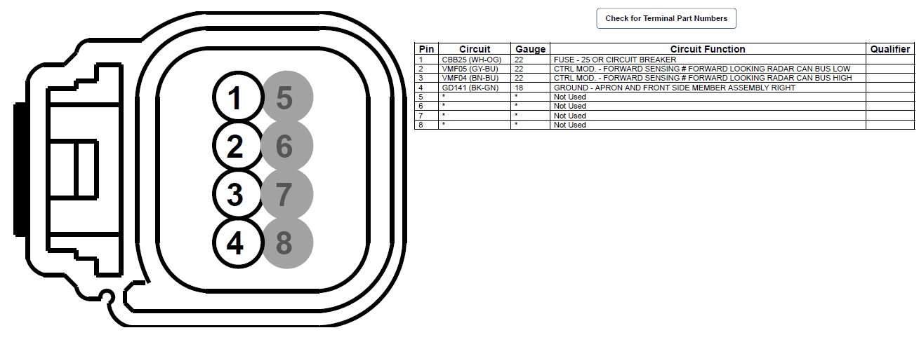
With the CCM harness pulled through to the CCM, we now need to splice the WPT1198 pigtail to the harness.
Below is the pinout for the CCM connector (C1582). This diagram is viewed as if you were looking into the face of the connector.
Finish wiring the IPMA
- Trace the wires on the back of the connector. Grab hold of wires 5, 6, 7, and 8. Twist them together and bend them off to the side. We will not need them and we can remove them. I do not have the tool to remove the unneeded terminals so I have cut the wires short and capped them for now.
- I always make the mistake of starting to splice wires before I pull heat shrink tubing on the wires. DON'T MAKE MY MISTAKE. Take the four wires for pins 1-4 and slide them through an appropriately sized heat shrink tube. Pull the wires all the way through so the tube does not shrink prematurely.
- With your CCM harness pulled through the bumper, cut off the excess, leaving 6-8" of slack.
- Strip the ends of the four wires from your CCM harness, and the ends of the four wires from the CCM connector pigtail.
- Before you proceed with splicing the wires, take care to match the pigtail wires with the correct harness wire. Mixing up the CAN bus wires will not allow the CCM to work.
- Slide the first wire from the pigtail all the way through a heat shrink solder connector. Take the corresponding harness wire and push the exposed strands into the exposed strands of the pigtail wire. Slide the solder connector back over the connection so it is centered on the solder ring and expose the connector to heat until the solder has melted.
- Repeat step 5 for each of the connections.
- Once all four wires are spliced and the connectors are shrunk, slide the heat shrink tubing over the all four connectors and shrink the tubing with the heat gun.
- Wrap the new connection and pigtail wires with harness tape, starting where your CCM harness tape wrap ends.
- Insert the CCM connector into the back of the CCM.
This was the most technically challenging step of this task. At a high level: we are going to disconnect the IPMA connector from the IPMA, open the connector, and insert our two new CCM wires.
With this finished, your wiring job should be complete. Congratulations!
- The first step is to strip the two wires hanging from the headliner near the IPMA. Only 1/4 to 1/2 an inch needs to be stripped.
- Insert each wire into a female pin terminal and crimp the terminal around the wire.
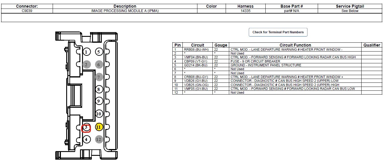
- Using the diagram below, insert the terminals into the appropriate space in the connector. CAN high is inserted in the slot for pin #3 (circled in red), and CAN low is inserted in the slot for pin #11 (highlighted in yellow). As with the CCM connector, the pins are numbered as if you are looking at the face of the connector.
- To insert the pin terminals, the connector must be opened. Each side of the connector has its own cover that must be released. To release the cover, use a small flathead screwdriver or pry tool and gently lift up each side of the cover. The cover folds back roughly 90-degrees.
- Once opened, the newly crimped pin terminals should slide in with minimal force needed.
- Since I did not have the correct terminals, I had to trim them to make them fit. There was a fin on the top that had to be removed to fit in the perfectly square hole in the connector.
- When the new pins are inserted, verify that CAN high is wired to pin #3 and CAN low is wired to pin #11.
Programming with FORScan
At the time of writing, the FORScan release available on the web for download does not support Maverick VINs for certain functions necessary for this procedure.
The FORScan team has given me permission to link to the test build they sent me for use with 2022 Mavericks: https://forscan.org/download/FORScanSetup2.3.48.test20220425.exe
I look forward to hearing everyone's experience doing this install. If I have left anything out, or any questions remain, I will do my best to monitor this post for discussion.
- Reconnect your negative battery terminal.
- Load FORScan and connect your OBD cable.
- Click the connect button in FORScan. If you have a saved profile for your truck already, do not use it. Using a saved profile causes FORScan not to scan all modules and it will not find the new CCM.
- When FORScan is finished connecting, you should see the CCM in the list of available modules.
- If you are new to FORScan, please find a video tutorial or walkthrough before attempting the changes below.
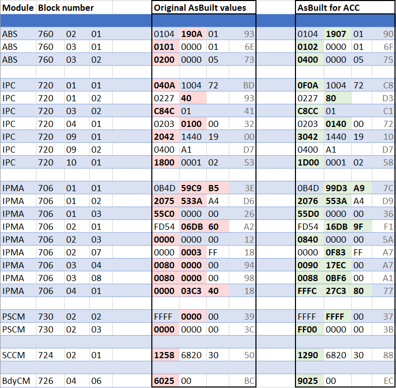
- Changed needed in FORScan are below. To make things easier to read, I put the checksum values (last two values in each row) in their own column. You can ignore these as FORScan recalculates the checksum when writing.
- But what about the CCM?! The CCM requires your VIN to be entered in hexadecimal values. To convert your VIN to hex, I used the following site: https://onlinehextools.com/convert-ascii-to-hex
- Uncheck "Add 0x hex prefix" as it makes the output easier to read.
- Paste your VIN in the "ascii" box and the hexadecimal equivalent should appear in the "hex" box.
- Now, use the following table to enter the VIN into the CCM module in FORScan. Replace the Vs with your hexadecimal VIN.

- Once you are finished writing changes, reset your DTCs.
- At this point, I would start re-assembling the bumper cover and other components disassembled above. You will need to do some driving to calibrate the CCM and (possibly) the IPMA.
- Next you will need to perform CCM calibration. This can be found in FORScan in the "Procedures" section.
- Follow the instructions on screen. You will need to drive to calibrate the sensor. You will have a warning in your instrument cluster until the calibration is finished, at which point the warning should disappear.
- Once this happens, find a safe place to park and clear your DTCs again.
- You may also need to calibrate the IPMA camera. This is also available in the "Procedures" section of FORScan, and it also requires some driving.
- If you have to calibrate the IPMA, you should also clear the DTCs when finished.
- At this point, I had ACC available in the cluster, I could enable cruise control from the steering wheel switch, but I could not select a speed and actually engage ACC.
- If this happens, try disconnecting the negative battery terminal for an hour or so.
No dealer will do it. DIY or maybe an aftermarket/stereo shop might - but likely most won't either due to liability and/or having to use ForScan. If you aren't able to DIY it, maybe you can find a shop to install the parts and wiring, then you code it afterwards.Very elaborate DIY. Only thing is I would never be able to accomplish this task myself. The question I have is will Ford do this for you?
I am using acc in my ecoboost since May 2024, the only issue is brake booster can’t hold the complete stop. it will stop to zero on a traffic jam situation , but it stop to zero and then starts going, and a message appears, “take the control “ and you need to press the brake to avoid the truck continues going, for normal traffic flow it works ok. The brake booster does a noise that I think is not present in electric.Only a Lariat with ACC or a Hybrid will have an electric brake booster. Some have added ACC to an EB without switching to the elctric brake booster but there could be issues with stop and go driving with ACC.
I cannot imagine any Ford dealership would ever be willing to do this for a customer. There is too much risk and it's too heavy of a modification. I mean, most Ford dealerships won't even install aftermarket brake pads or a cold-air intake. Even though these are Ford parts, this is not something officially supported by Ford or their dealers by any means.Very elaborate DIY. Only thing is I would never be able to accomplish this task myself. The question I have is will Ford do this for you?
Hi ,It's amazing the job you did. I have a lot of doubts since my trim is a little different (i am in Argentina). I have a 2024 Lariat FX4 Ecoboost. This includes Copilot 360, brake assist and emergency auto brake buy doesn't include lane assist or adaptative cruise control. My grill doesn't have that square part in the low part but i think that it should have some kind of radar for the auto brake? or not? What do you think?
| Part | Desc | Price Per | Qty | Total |
|---|---|---|---|---|
| W506976-S450B | Self-tapping screws | $2.73 | 3 | $8.19 |
| NZ6Z-9E731-A | Sensor Assembly - Speed | $404.06 | 1 | $404.06 |
| NZ6Z-14C022-A | Bracket | $30.29 | 1 | $30.29 |
| NZ6Z-17E810-AA | CCM cover | $22.00 | 1 | $22.00 |
| WPT-1198 | 8-pin pigtail for radar sensor | $53.52 | 1 | $53.52 |
| SW8585 | Adaptive cruise control steering wheel buttons | $50.79 | 1 | $50.79 |
| LU2Z-14474-AA | Female pin terminal for modifying the IPMA harness connector | $6.91 | 2 | $13.82 |
| LB5Z-13341-BA | Turn Signal Switch for Lane Keep Assist | $72.31 | 1 | $72.61 |
| - | - | - | - | - |
| Optional | ||||
| NZ6Z-8200-DA | Lariat grill w/ speed sensor (not really needed) | $209.21 | 1 | $209.21 |
| NZ6Z-8312-A | Radiator Support Air Deflector (makes install easier) | $113.45 | 1 | $113.45 |
| - | - | - | - | - |
| Odds and Ends | ||||
| B0B8JK65Q6 | XFasten Wire Harness Tape | $7.99 | 1 | $7.99 |
| E352JP | 4pcs 12V-24V Add-a-Circuit Micro2 Fuse Tap | $6.99 | 1 | $6.99 |
| B0CT88MHXQ | TKDMR 2.2" Heat Shrink Tubing Kit | $13.67 | 1 | $13.67 |
| 25' GXL 18g wire | 4x 25' 18g auto GXL wire (Red/Black/Yellow/Green required) | $30.95 | 1 | $30.95 |
| Wire strippers | Buyers choice (Klein example, I have these) | |||
| Crimp tool | Buyers choice (example, you need heat shrink jaws) |
add LB5Z-13341-BA for lane keep assist (replaces turn stalk), since you don't have CP360.Hello, I'm hoping this is still active. I'm looking at getting any updated parts together for this. I have a 2023 hybrid XLT without CP360.
Looks like I need (from original post, will edit with NEW information here for others):
Part #'s include a link to the part for easy ordering.
Part Desc Price Per Qty Total W506976-S450B Self-tapping screws $2.73 4 $10.92 NZ6Z-9E731-A Sensor Assembly - Speed $370.61 1 $421.06 NZ6Z-14C022-A Bracket $51.62 1 $59.66 NZ6Z-17E810-AA CCM cover $17.66 1 $22.00 WPT-1198 8-pin pigtail for radar sensor $21.19 1 $53.52 SW8585 Adaptive cruise control steering wheel buttons $56.58 1 $50.79 LU2Z-14474-AA Female pin terminals for modifying the IPMA harness connector $6.91 1 $6.91 ?? What else am I missing? ? ? ? - - - - - Optional NZ6Z-8200-DA Lariat grill w/ speed sensor 209.21 1 $209.21 NZ6Z-8312-A Radiator Support Air Deflector $113.45 1 $113.45 - - - - - Odds and Ends WHBL-3450F3 XFasten Wire Harness Tape $9.99 1 $9.99 E352JP 4pcs 12V-24V Add-a-Circuit Micro2 Fuse Tap $6.99 1 $6.99 B07C3NBTJ9 Marine Grade Heat Shrink Wire Connectors $8.49 1 $8.49
I plan to film this and upload to YouTube (I receive no monetary compensation for this, I'm not an "influencer") to help others out, but want a solid list before I start ordering and hacking into my Maverick.
THANK YOU for helping me (and many more in the future!) out.
I actually have that turn stalk as I added it previously! But have added it to the list for others as well.add LB5Z-13341-BA for lane keep assist (replaces turn stalk), since you don't have CP360.
List looks just like mine, otherwise. Prices are decent too (I'm assuming these are current).
I recommend going back a few pages and finding the pdf I made - I think it is an updated version of the OP with useful items added where necessary. Also easy to print or display on screen for reference while working.
The best thing to use is GXL wire for the thermal/fire performance. I think I used 18ga for all 4 since 22ga is harder to find. You can buy small quantities on eBay and Amazon or somewhere like McMaster-carr. When you have your pieces laid out, wrap them all together with Tesa tape to make a harness.Hello, I'm hoping this is still active. I'm looking at getting any updated parts together for this. I have a 2023 hybrid XLT without CP360.
Comma.ai post
Surfstar PDF @surfstar
Looks like I need (from original post, will edit with NEW information here for others):
Part #'s include a link to the part for easy ordering.
Part Desc Price Per Qty Total W506976-S450B Self-tapping screws $2.73 4 $10.92 NZ6Z-9E731-A Sensor Assembly - Speed $404.06 1 $404.06 NZ6Z-14C022-A Bracket $59.66 1 $59.66 NZ6Z-17E810-AA CCM cover $22.00 1 $22.00 WPT-1198 8-pin pigtail for radar sensor $53.52 1 $53.52 SW8585 Adaptive cruise control steering wheel buttons $50.79 1 $50.79 LU2Z-14474-AA Female pin terminals for modifying the IPMA harness connector $6.91 1 $6.91 LB5Z-13341-BA Turn Signal Switch for Lane Keep Assist $72.31 1 $72.61 ?? What else am I missing? ? ? ? - - - - - Optional NZ6Z-8200-DA Lariat grill w/ speed sensor $209.21 1 $209.21 NZ6Z-8312-A Radiator Support Air Deflector $113.45 1 $113.45 - - - - - Odds and Ends WHBL-3450F3 XFasten Wire Harness Tape $9.99 1 $9.99 E352JP 4pcs 12V-24V Add-a-Circuit Micro2 Fuse Tap $6.99 1 $6.99 B07C3NBTJ9 Marine Grade Heat Shrink Wire Connectors $8.49 1 $8.49 ? 22g wire 3x, 18g wire 1x, for wiring harness ? ? ?
Suggestions for 22g wire 3x, 18g 1x?
THANK YOU for helping me (and many more in the future!) out.
