- First Name
- Pete
- Joined
- Feb 25, 2024
- Threads
- 7
- Messages
- 74
- Reaction score
- 53
- Location
- Connecticut USA
- Vehicle(s)
- Maverick
- Engine
- 2.0L EcoBoost
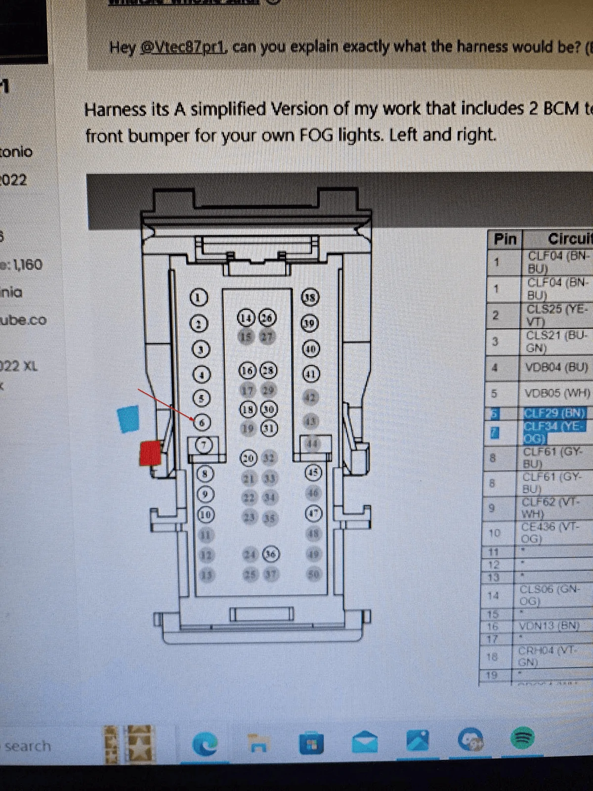
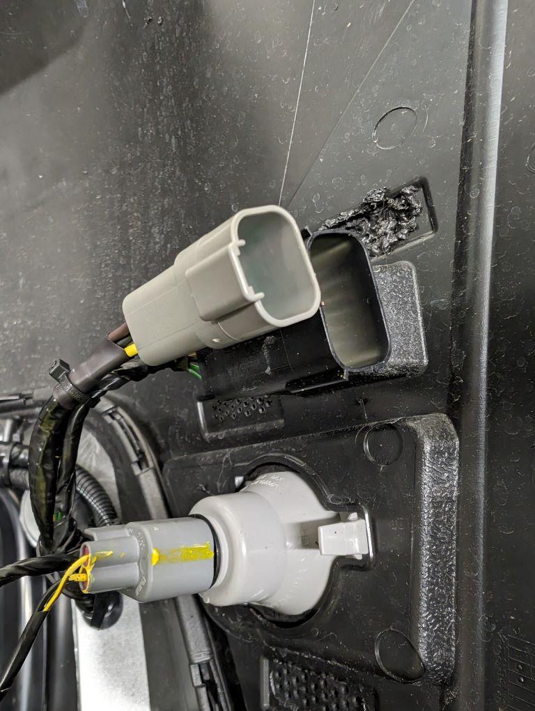
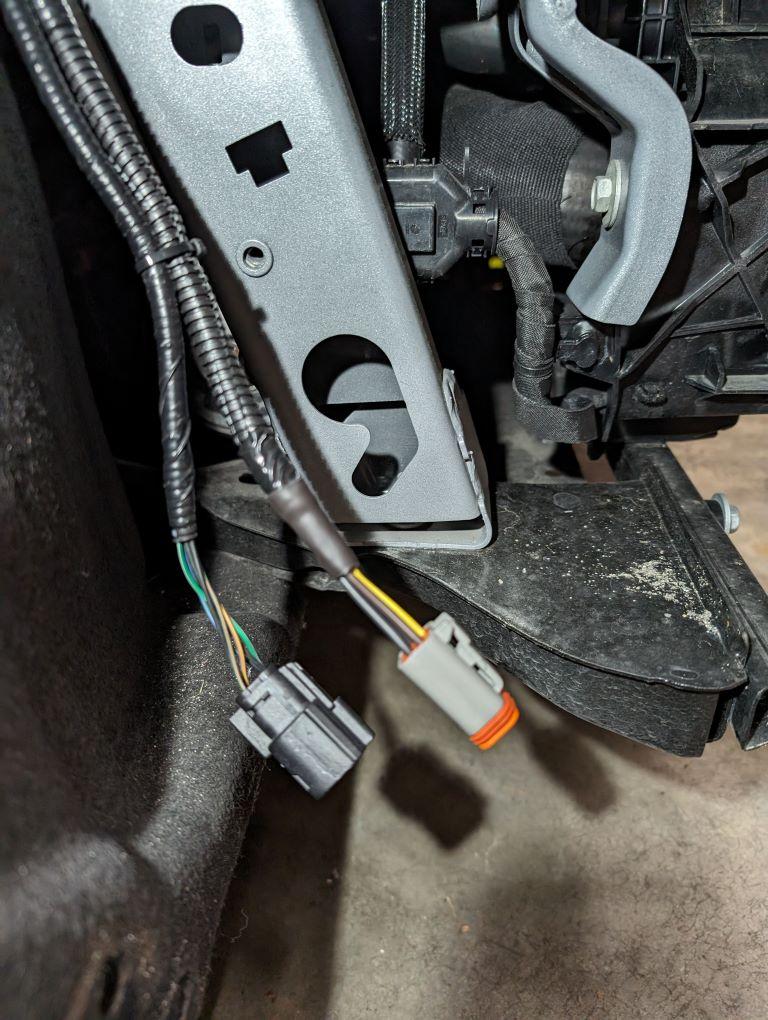
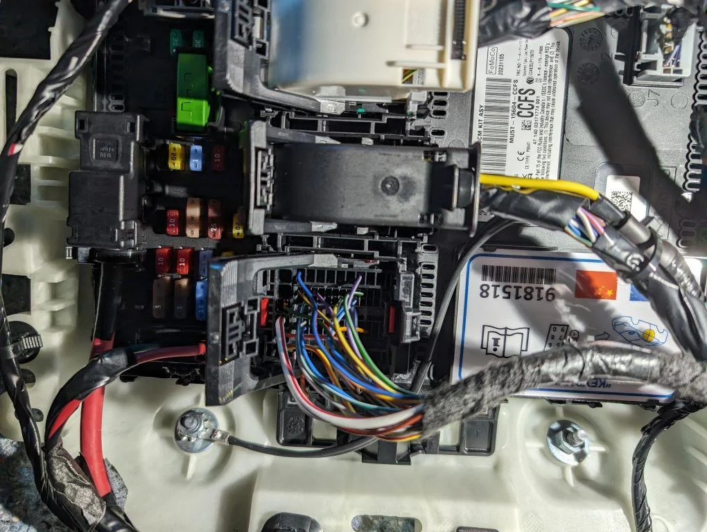
this is great info. @Vtec87pr1 are you able to check the ford pro tech system for the PN for the bumper harness connector? shown in the manual as connector c121.Thats a great idea . Great job finding those.
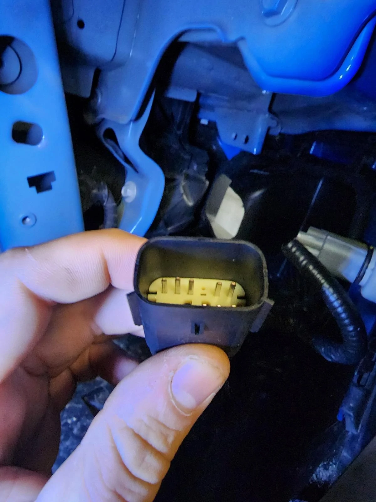
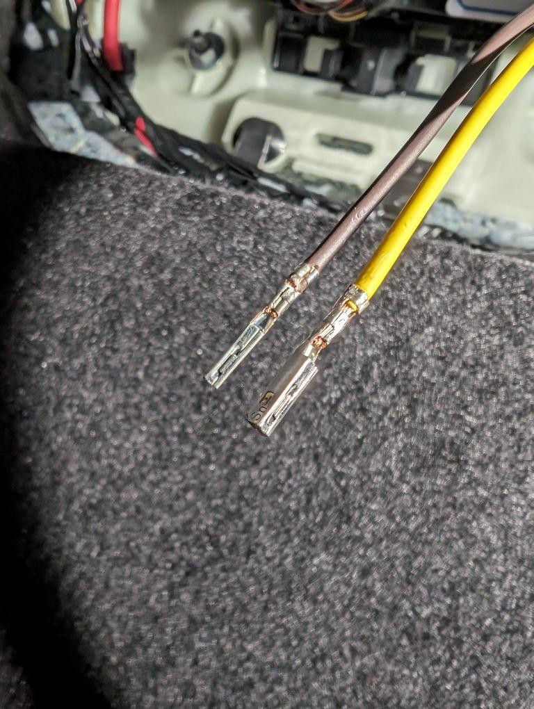
im looking for a PN for this connector and its pins to do what you did..
i think this molex connector from ebay will work but id like to confirm...
Ebay Molex Connector
Sponsored