
- Thread starter
- #1
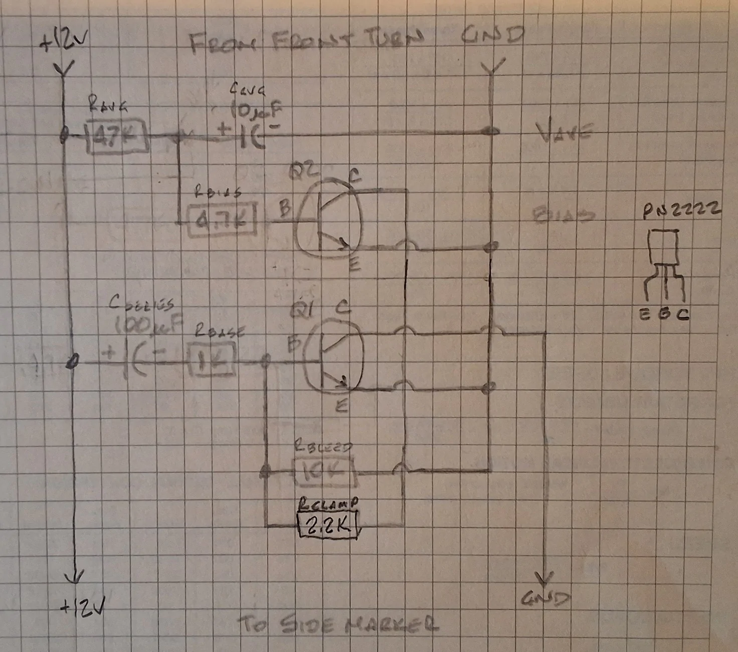
Those that have followed snowcatxx87’s post (https://www.mavericktruckclub.com/f...gnal-at-100-no-low-beam-working-xl-xlt.44434/) to change your DRL’s to your front turn signals have found that if you also have side badge turn signals, these are also on as DRL’s. I have created a filter for the side badge turn signals to make them come on only for the turn signal function.
Doing this project, I found that the DRL signal is not a constant 12vdc. For whatever reason it is a PWM (Pulse Width Modulated) signal. This required two parts for this filter circuit. One to detect the high pulses (DRL ON) and one that will allow the side badge turn signals to flash (DRL OFF).
The turn signal light ON feed builds up a DC voltage when the feed is steady/on (DRL). This DC turns ON the detector transistor Q2 which pulls the base of the switching transistor Q1 to ground, preventing base pulses from turning it ON. This keeps the side badge light LED OFF.
When the feed is blinking (turn signal ON), the averaged DC is low and Q2 stays OFF. Q1 receives turn signal pulses via the coupling capacitor. This blinks the side badge light LED.
I created these circuits (one for each side badge) and hot glued them to the inside of the badges. I think they should be pretty much protected there. At least I am hoping. Time will tell.
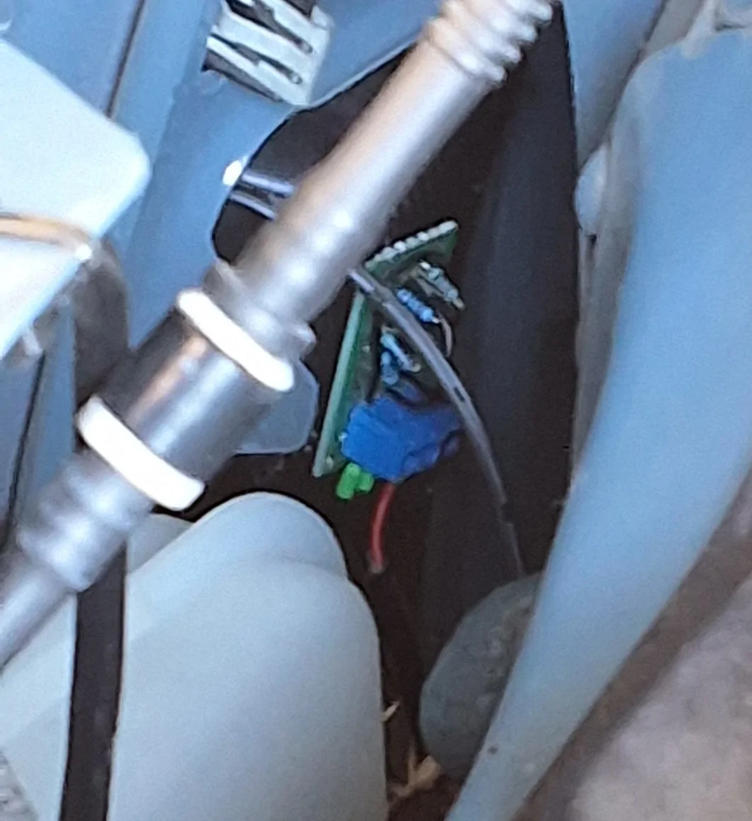
I realize this project isn’t for everyone. Those that have the skills can knock each board out in about 45 minutes. If you do want to tackle this project, make sure your LED or whatever light you are using is under 150mA continuous. I am using a 6 LED SMD-3528 for each of my side badge lights which draw under 70mA.
I like how my Maverick now mimics the F150 yellow DRL/Turn signals. Much cheaper to replace than the headlights.
Doing this project, I found that the DRL signal is not a constant 12vdc. For whatever reason it is a PWM (Pulse Width Modulated) signal. This required two parts for this filter circuit. One to detect the high pulses (DRL ON) and one that will allow the side badge turn signals to flash (DRL OFF).
The turn signal light ON feed builds up a DC voltage when the feed is steady/on (DRL). This DC turns ON the detector transistor Q2 which pulls the base of the switching transistor Q1 to ground, preventing base pulses from turning it ON. This keeps the side badge light LED OFF.
When the feed is blinking (turn signal ON), the averaged DC is low and Q2 stays OFF. Q1 receives turn signal pulses via the coupling capacitor. This blinks the side badge light LED.
I created these circuits (one for each side badge) and hot glued them to the inside of the badges. I think they should be pretty much protected there. At least I am hoping. Time will tell.
I realize this project isn’t for everyone. Those that have the skills can knock each board out in about 45 minutes. If you do want to tackle this project, make sure your LED or whatever light you are using is under 150mA continuous. I am using a 6 LED SMD-3528 for each of my side badge lights which draw under 70mA.
I like how my Maverick now mimics the F150 yellow DRL/Turn signals. Much cheaper to replace than the headlights.
Sponsored
Last edited:
