- Thread starter
- #1
Hey MTC,
I'm planning on installing a DC-DC charger in the mav, so I can recharge my trailer battery while driving. There a few questions/satiny checks I'd love some help with, and cheers if others have considering the same thing!
The plan to go with the Victron Orion XS DC-DC charger since it's smaller, doesn't run as hot, and lets you customize a specific per amp battery charge rate (up to 50A). Below is a wiring diagram and a walk-through of the system.
Please let me know if you have any thoughts and/or input on the questions.
Thanks!
Main Questions:
Confirming the output of the "high-output" alternator is 175 amps
How "bad" would it be to run 50A with the below setup?
Any preferred spots to run a thin, signal wire from the driver's side dash into the engine bay?
Is it worth it to ground the negative cable between the charge controller and trailer plug? (wiring diagram)
What am I missing?
The Details:
Starting at the Truck's battery...
Wiring Diagram:
Thanks for any help!
I'm planning on installing a DC-DC charger in the mav, so I can recharge my trailer battery while driving. There a few questions/satiny checks I'd love some help with, and cheers if others have considering the same thing!
The plan to go with the Victron Orion XS DC-DC charger since it's smaller, doesn't run as hot, and lets you customize a specific per amp battery charge rate (up to 50A). Below is a wiring diagram and a walk-through of the system.
Please let me know if you have any thoughts and/or input on the questions.
Thanks!
Main Questions:
Confirming the output of the "high-output" alternator is 175 amps
This is the one for trucks with 120V outlets in the cab/bed
I found LX6Z10346E as the right part number, giving a rating from this Ford parts page
How "bad" would it be to run 50A with the below setup?
Only when rpms stay high so it doesn't overheat (restrict changing at idle: helpful video for charging with alternators)
It would still be running semi-continuously for up to 4 hours to fully charge my battery
Please let me know if you have a recommendation for a better amperage to set in the charge controller
Any preferred spots to run a thin, signal wire from the driver's side dash into the engine bay?
Small ~16 AWG from the on/off button for the relay
Is it worth it to ground the negative cable between the charge controller and trailer plug? (wiring diagram)
My thought, is that it helps balance any voltage potential between the negatives of the truck chassis and trailer frame. Plus, it couldn't really hurt.
However, the trailer coupler and truck hitch could already accomplish this already, ignoring whatever interference from the grease...
What am I missing?
Just looking for a 2nd set of eyes and sanity check before I get started.
The Details:
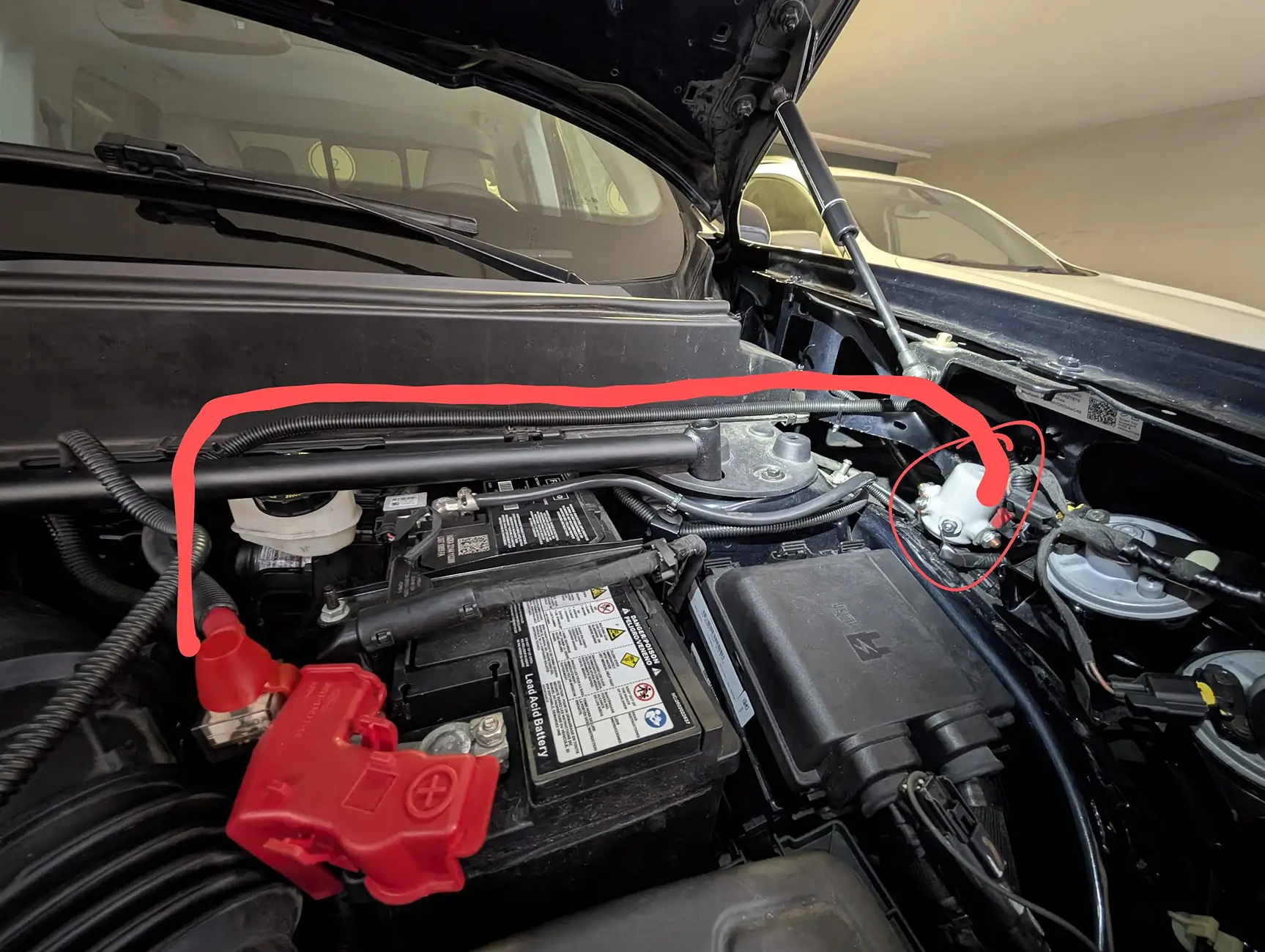
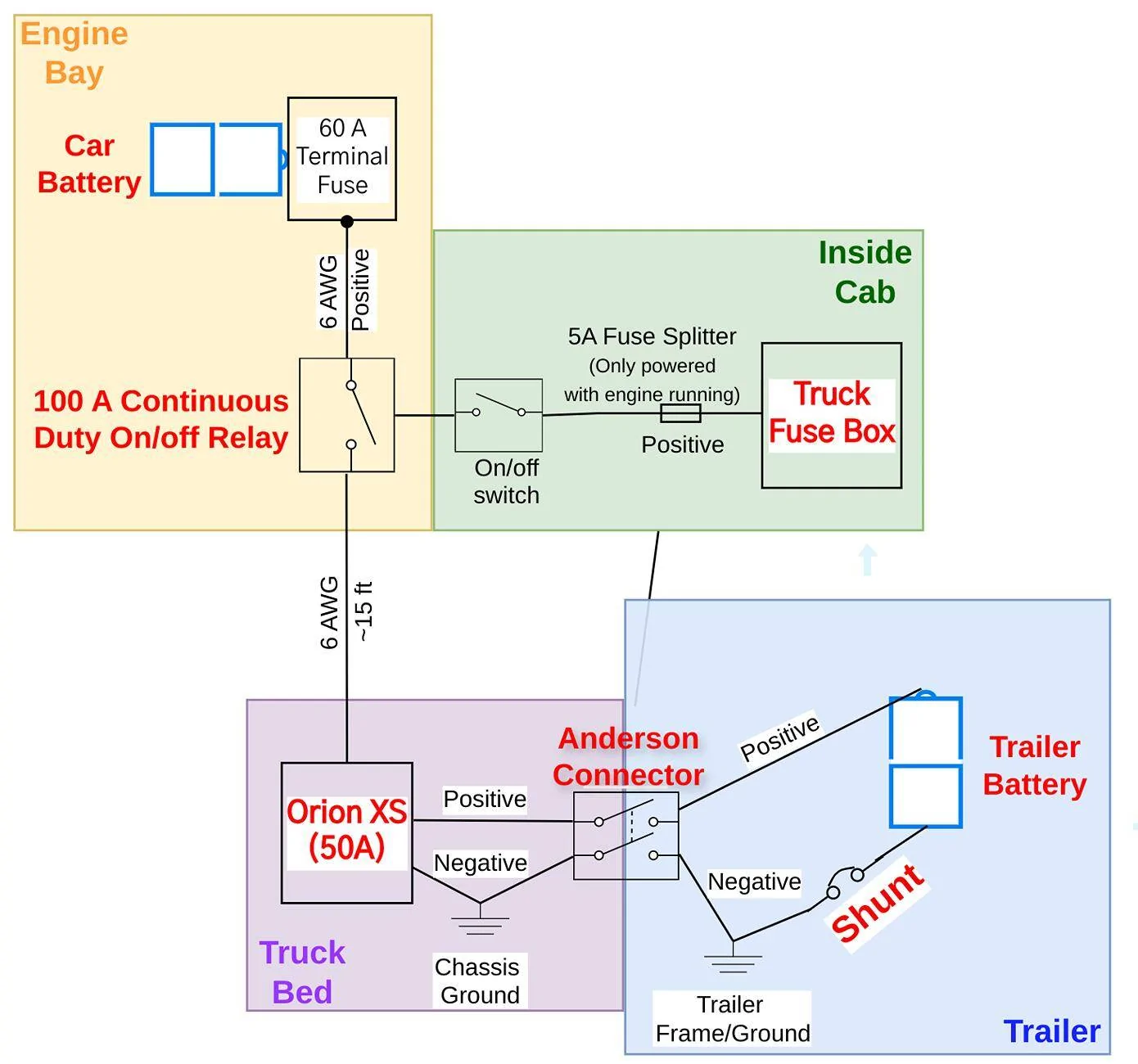
Starting at the Truck's battery...
- 60 A terminal fuse on the battery's positive bus
- 4 AWG marine grade, tinned copper cable (used everywhere)
- Sealed, UL Rated 100A continuous duty relay (normally open) mounted near the battery in the engine bay
- Relay activated via a push button on/off switch in the truck cab. It stays "on," even after pit stops.
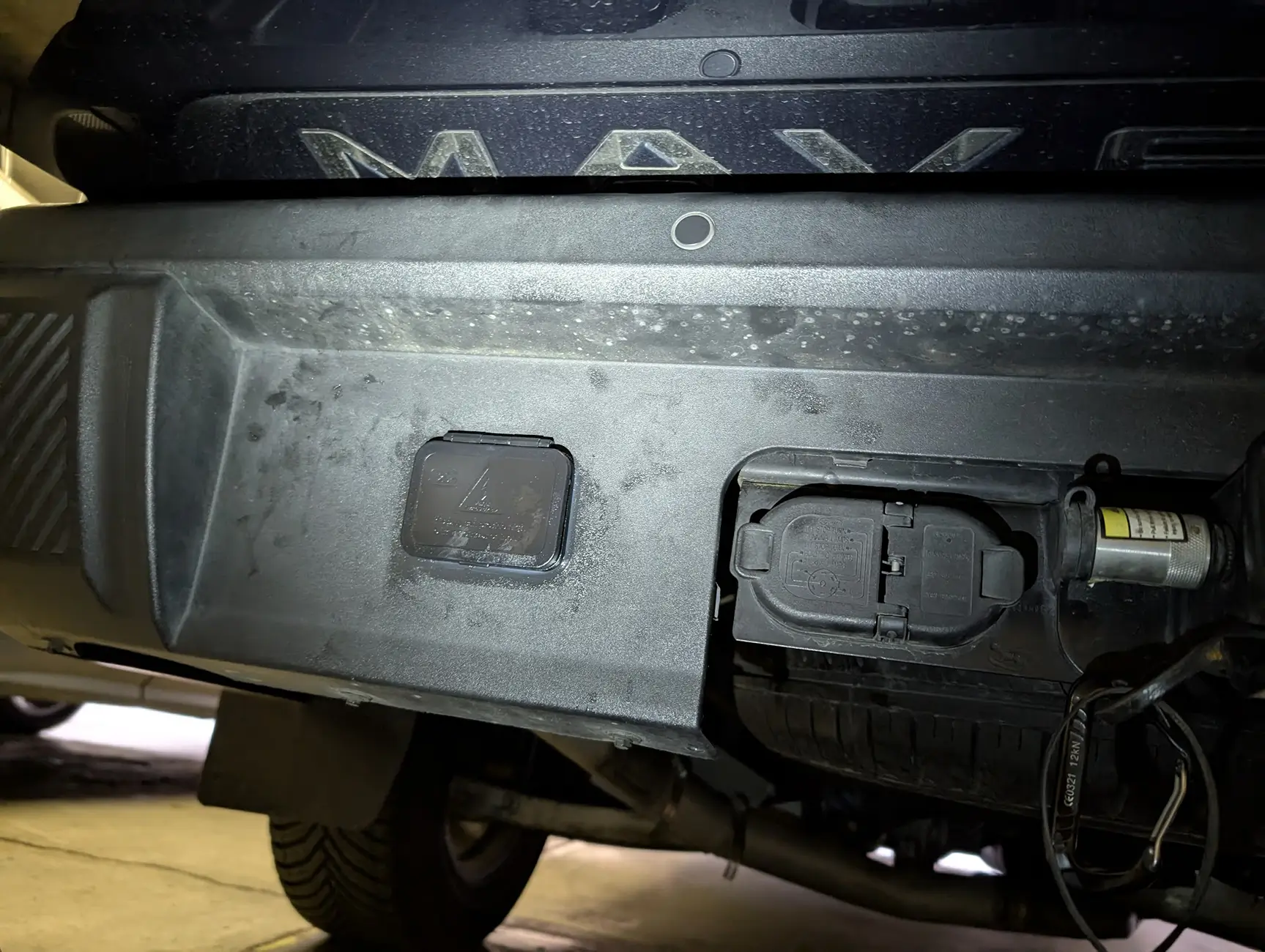
- The truck battery hopefully won't die since the switch will only be powered when the engine is running; via a fuse splitter inside the cab's fuse box - Cable goes from the from the relay, under the truck, and to the cubby in the truck bed
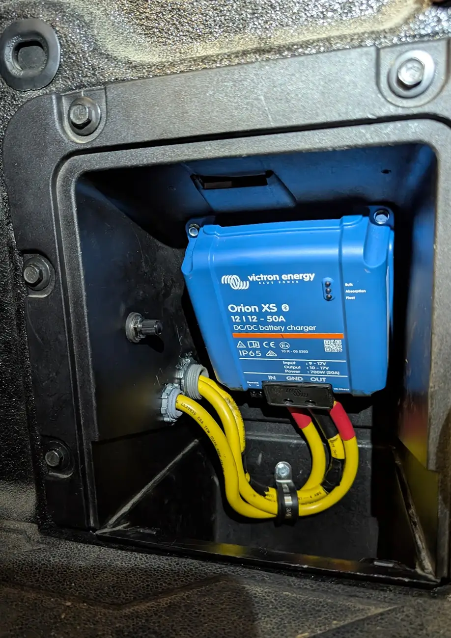
- A Victron Orion XS DC-DC charge controller is mounted in the truck's cubby. They're smaller and run cooler than a 30A system (with a steep cost bump)
- This is connected to a 120A Anderson plug mounted near the hitch
- The trailer side of the plug is connected to the battery (positive) and the frame/shunt/battery (negative)
Wiring Diagram:
Thanks for any help!
Sponsored