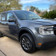

- Thread starter
- #1
So you want warm hands in the winter?
Here's how to enable heated steering in a 2025 XL.
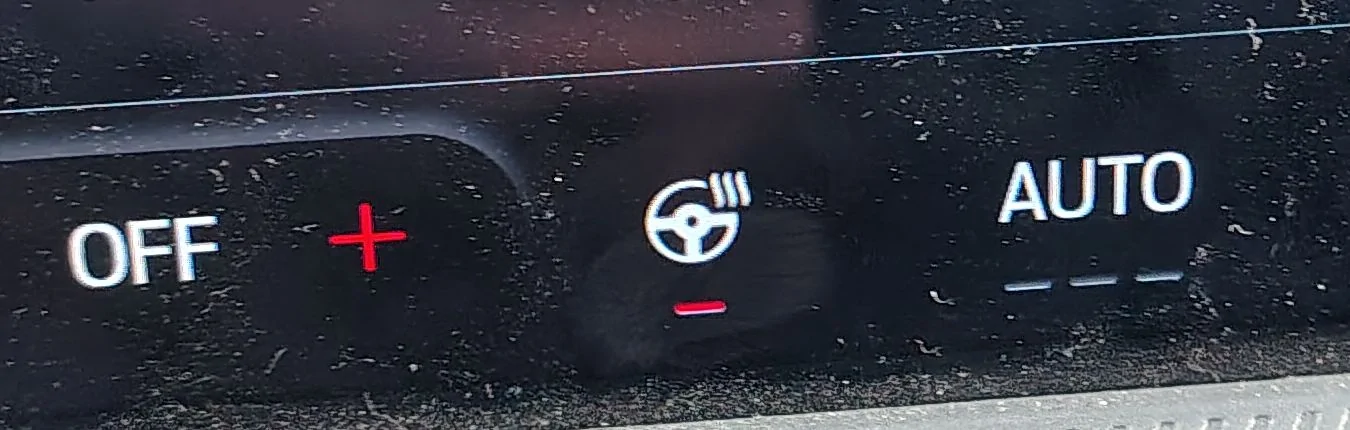
First let me say thank you to all the members that supplied diagrams to me over the different threads (connectors, harnesses and codes).
Also thank you to the original poster for previous models- see his work here: https://www.mavericktruckclub.com/f...eated-steering-wheel-to-an-xl-maverick.39185/
QRD
1. need 12 volt power from an ignition switched source.
2. the matching connector to provide the power to the wheel ( WPT - 404 )
3. the matching hardware (heated wheel and steering control module SCCM).
4. Forscan settings in HVAC, SCCM and IPC.
* as the sync 4 system eliminated the physical hvac buttons you wont need anything else.
NEEDS
Compatible sccm (the ending suffix of the part numbers tells you... See more below)
wiring harness and 2.8 pin (see ebay listings)
A heated capable steering wheel.
And forscan.
I had previously purchased a heated wheel for the adaptive cruise control upgrade. The wheel came with the buttons for adaptive cruise at the same price as just buying the buttons.
For the sccm, search junkyards for totaled lariats. Then check eBay for the matching vin a lot of the times they aren't listing them by the part number, or even if it's heated steering! I paid 110 for the sccm.
Wiring:
On 2025 they did not include the wiring from the battery junction box to the cabin. You will need to run a wire from the engine fuse box into the cabin (Unless you got lucky or have a higher trim where the wire is present). In equipped models and previous years they used the c200 harness at the driver's footwell - the wire comes from the engine bay to the connector then to the steering wheel. So check your harnesses first for that yellow green wire.
*Also note just like with the battery junction box, Ford did do some flipping of placement of the c200 and c201(top or bottom harness). The related wiring diagrams are posted by members for me while I was researching this and can be found with the search function.
For the wiring I purchased off eBay "Ford F-150 2021-2026 Heated Steering Wheel Harness Kit Connector Retrofit US" (random listing in image↓)
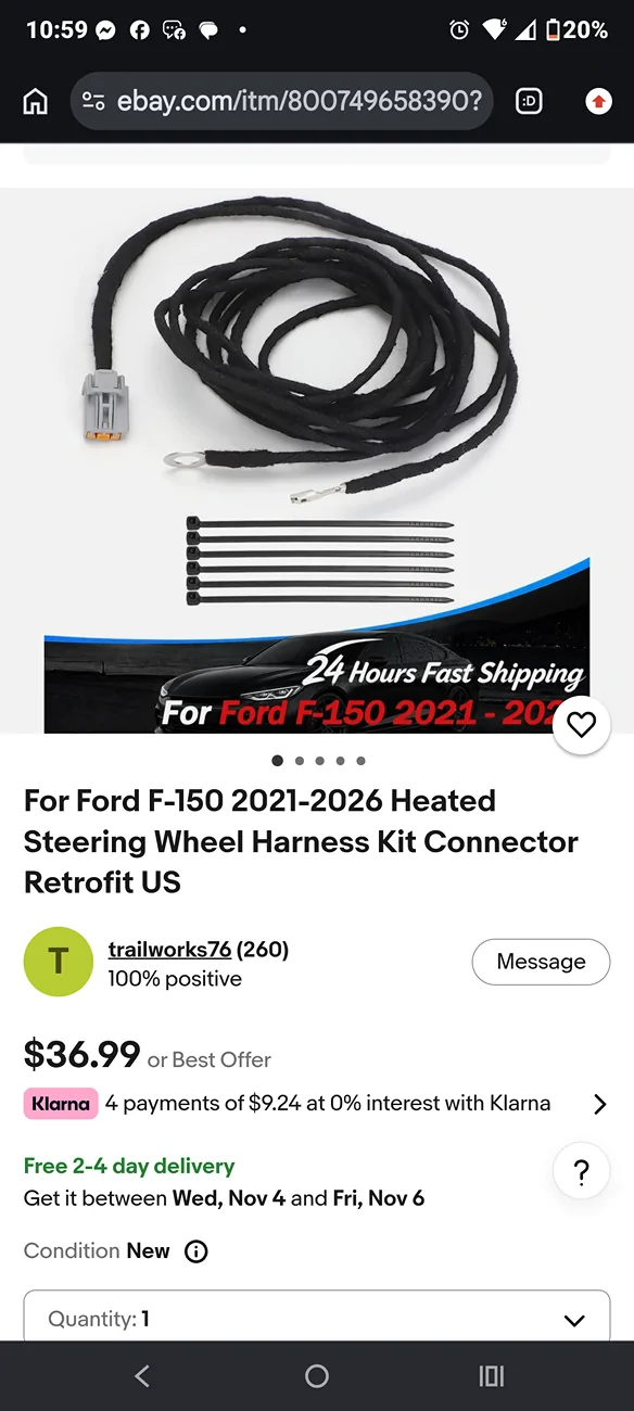
^ as you can see it has the connector, ground connector and 2.8 pin already done for you.
Ok so here's how I did it. First identify fuse circuit 160 in the fuse box going to connector
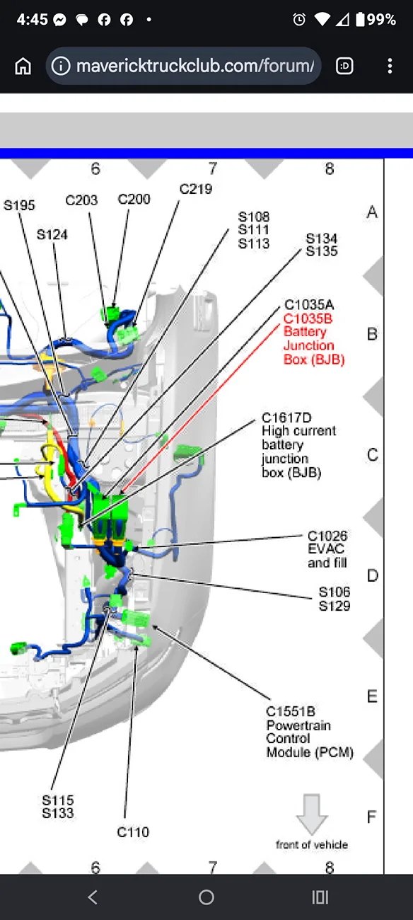
C1035a (warning I found that Ford on different years changed the placements i.e. by the engine can be B or A).
There should be a fuse in place (15 amp)
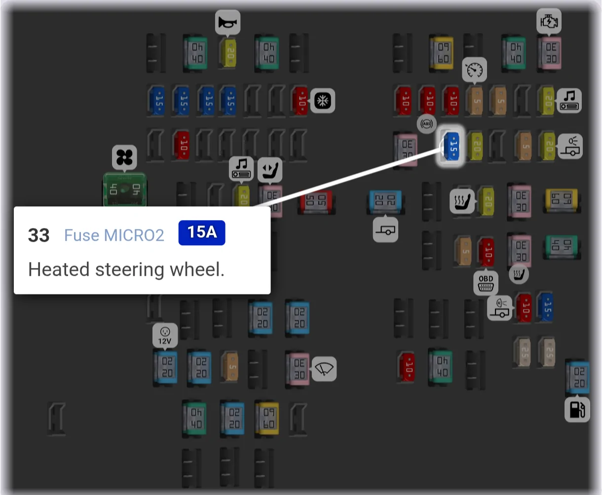 ^fuse #33 in the box. (Fuse 160, don't screw up and look for fuse 33 in the wiring diagrams...like I did for a hot minute).
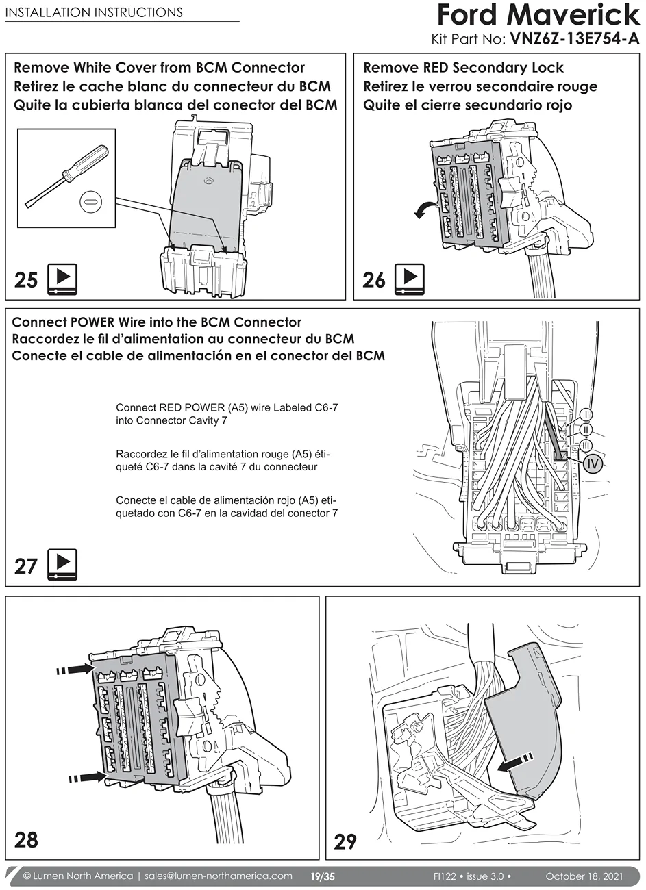
You should be able to find a pin without the matching wiring in the connector for the harness (see pdfs for more detail) but you're looking for
CBBG0
(YE-GN) 18 FUSE - 160 OR CIRCUIT
BREAKER
Pin 34 (for 2025 it's in the one by the engine/ guessing it's always that side). *Every diagram I've seen per year does have it as pin 34 regardless of it being c1035A or c1035B. (Images just below my digression about wiring).
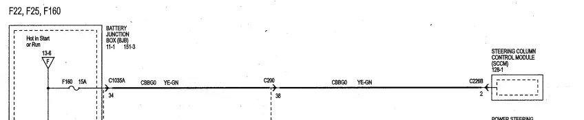
(^above photo of previous years wiring diagram. from the fuse box is CbbG0 and after the c200 harness it can be labeled CBB33 or remain CBBG0)
The pin: #34. Is a circuit that turns on with remote start and or the key.
Also of note the wheel draws 7.5 amps so the 15 amp circuit is more than enough and you could probably power a dash cam or something else with this.
There is an alternative passenger compartment fuse you can tap, but the micro3 taps suck.(I bought one off Amazon and the reviews are accurate you need a vice to press them in evenly and smoothly or it will break. The outer leg is in fact powered by both fuses, which is acceptable if you use that fuse slot as only of the two fuses on the micro3 is in fact in use).
First pic here is both sides of the battery junction box (fuse box). The left side is the engine side. When you look in you will see numbers stamped on the plastic for example 20 & 26. Those numbers are adjacent to that pin number to aid in counting and placement of the other pins.
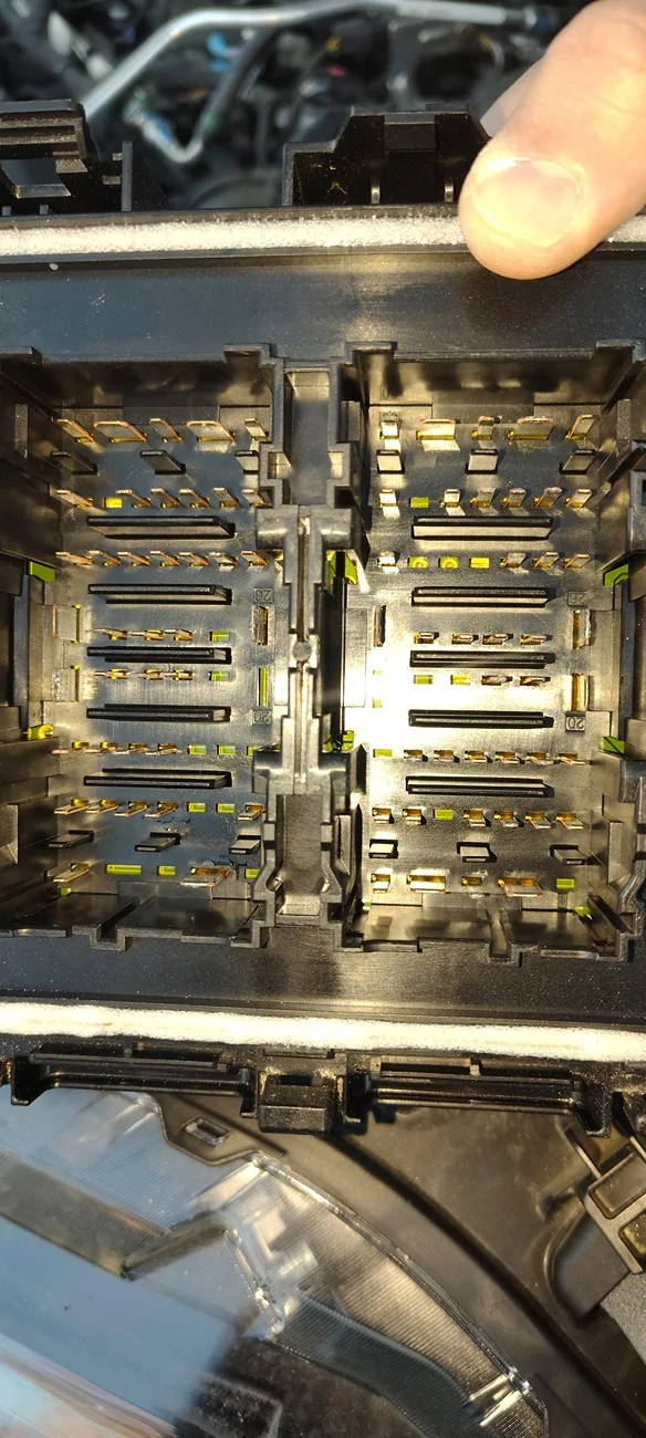
Closer to the engine In my case (left side)
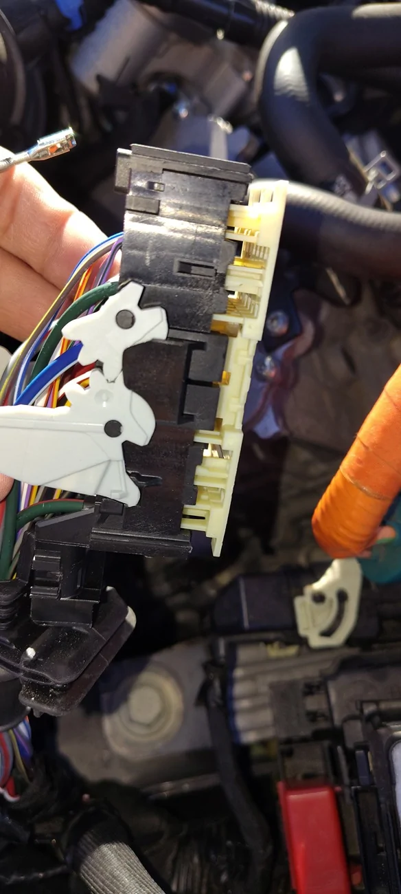
You'll slide that piece forward to insert the wire
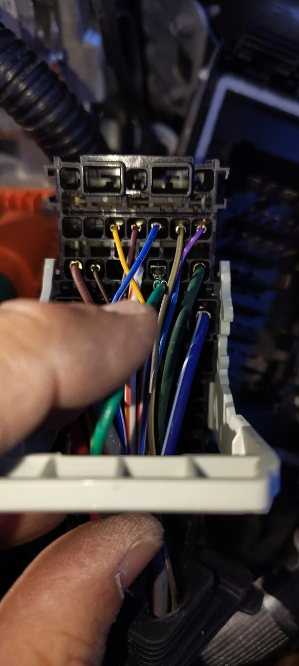
^remember when looking at the pdf it's from the other side. From this view it's the third slot from the right. From the front of the harness it's the opposite.
It's push to click then reassemble the harness. (if you need a replacement harness because you really screwed up its connector "wire assembly WPT-1739")
Ok but what about the wire you say.
That eBay listing has the connector (2.8 sized already installed). I did wrap the whole engine side in electrical tape to cover the felt.
Now there's an access panel/grommet that you can use (big oval, but it won't seal) or fish it from the passenger compartment (driver's side) following the existing wiring harness. I used a reusable plastic straw to guide it through the rubber (rolled back the rubber onto it) (see the blue straw below)
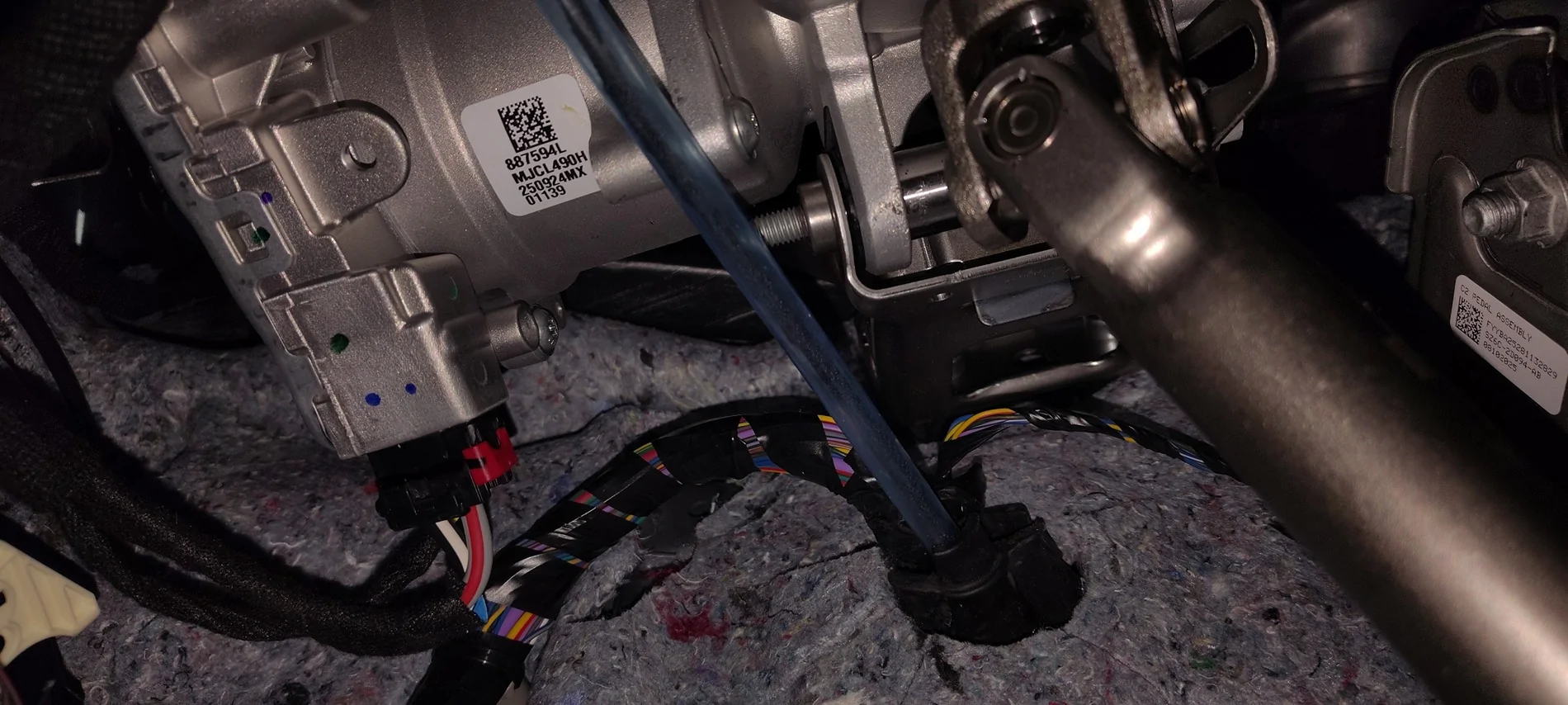
Now I would have preferred coming from the engine side, because I ended up cutting the straw as it would have otherwise been on the wire forever. (you really only need a few inchs of the straw.)
Once you have the wire through retape everything so it's nice looking again. I followed the existing harness all the way to the fuse box. The rubber boot on the fuse box wasn't to tight and I was able to push that pinned end right through into the harness (pics further down).
The ground wire took me a few minutes to find. There is a good one behind the light switches
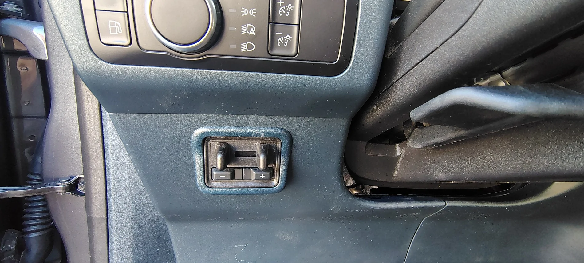 that you can see from some angles but I was absolutely unable to photograph. I didn't want to take all the paneling off; so I did it blindly. Reaching in from the footwell/steering column its accessible. It's an 8mm bolt. Use a ratchet extension and you'll have plenty of space to turn the ratchet. It took longer to find it than to actually attach to it. Once you see it, it's obvious and easy.
Ok now for remove your steering wheel, some people say disconnect your battery ground, I say disconnect your battery positive (everything is still grounded anyway) wait 15 minutes. Then turn wheel, push the buttons from the back side with your screwdriver to pop out the air bag. Use your 15/16 (double check this sizing) ratchet to remove the steering wheel bolt. Unplug the harnesses. Get to that sccm take the 4 bolts off. Remove and replace.
Before ordering a new module, you can check your truck's factory-installed clockspring. When you pull off the steering wheel shroud or look directly at the front face of your existing clockspring assembly:
The new SCCM is below this first pic. First pic is the old one still in place.
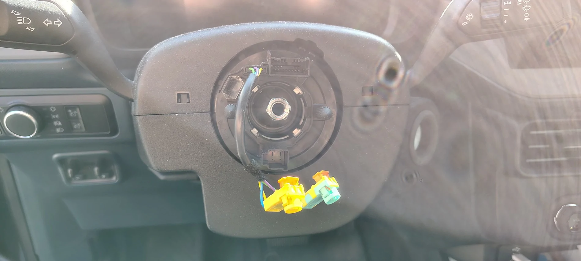
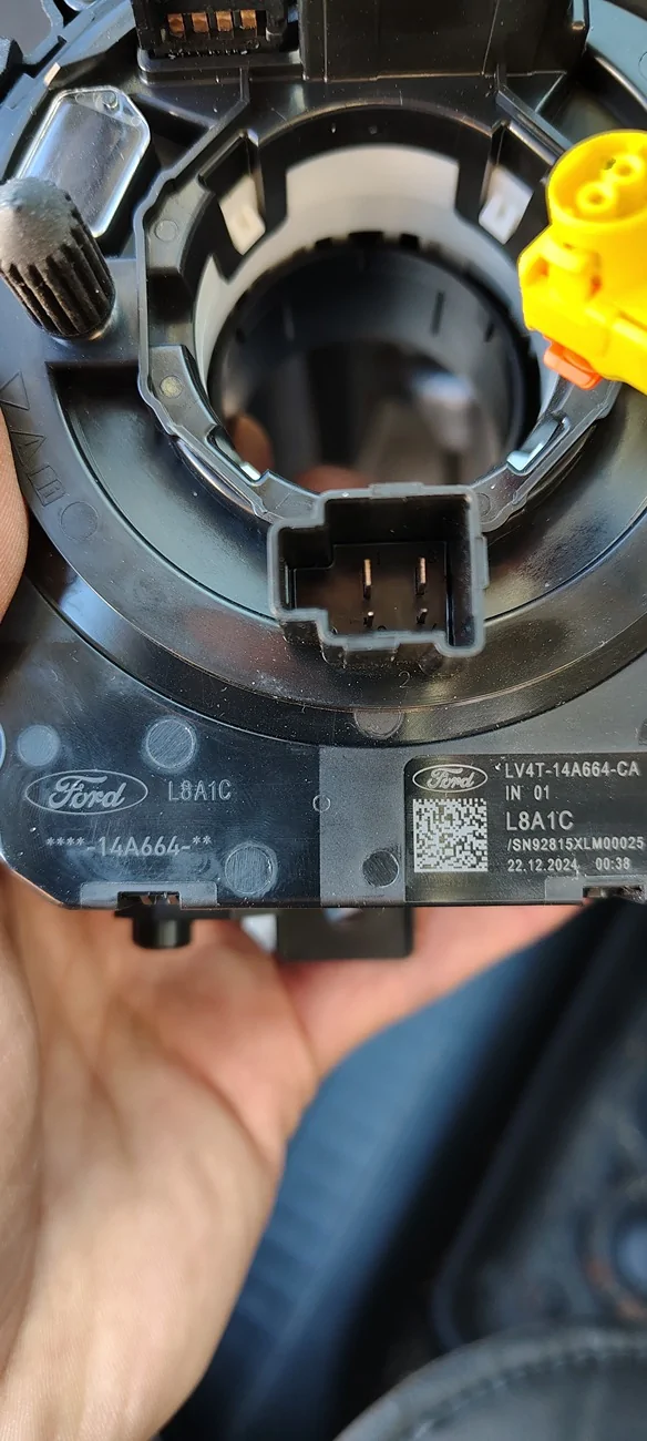
^steering wheel side plug (maybe yours already came with the correct SCCM)
below are the part numbers
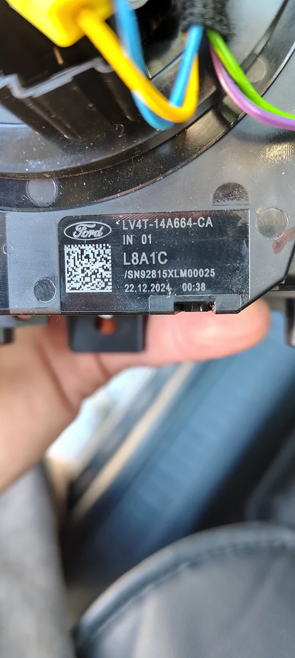
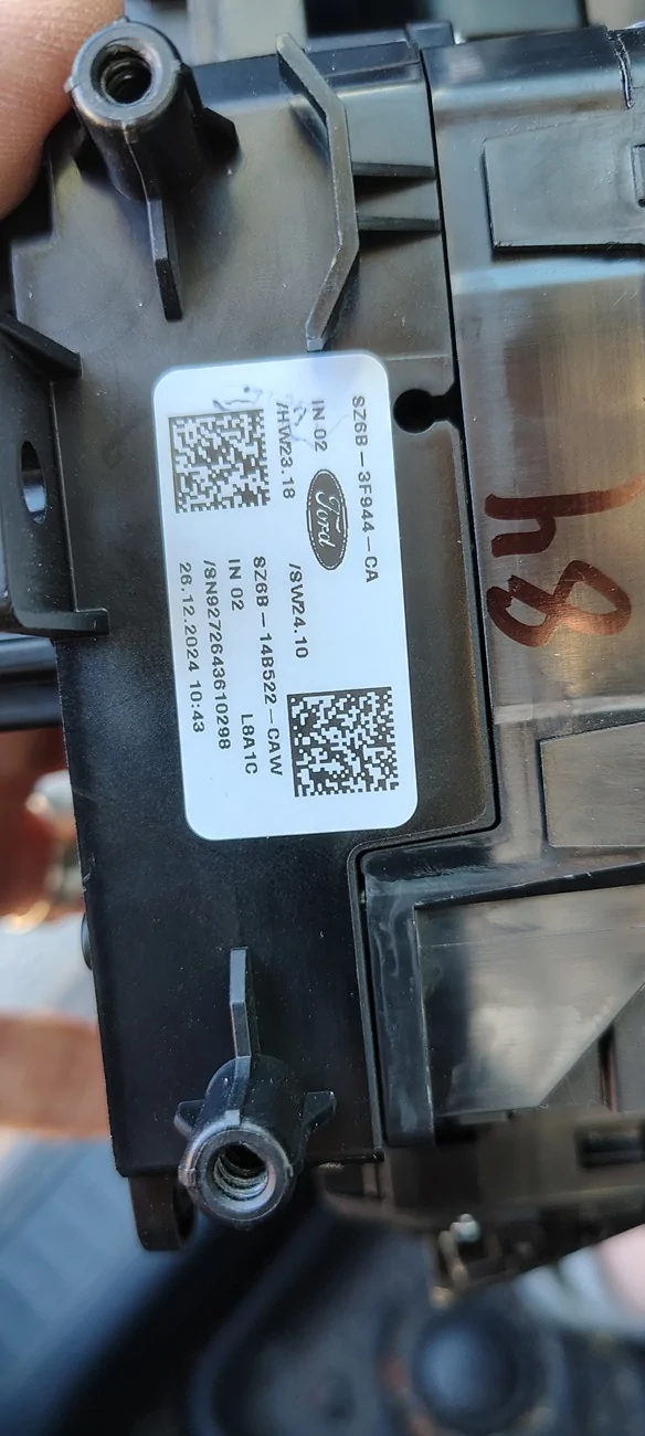
the new one backside the two prong harness is what you're looking for.
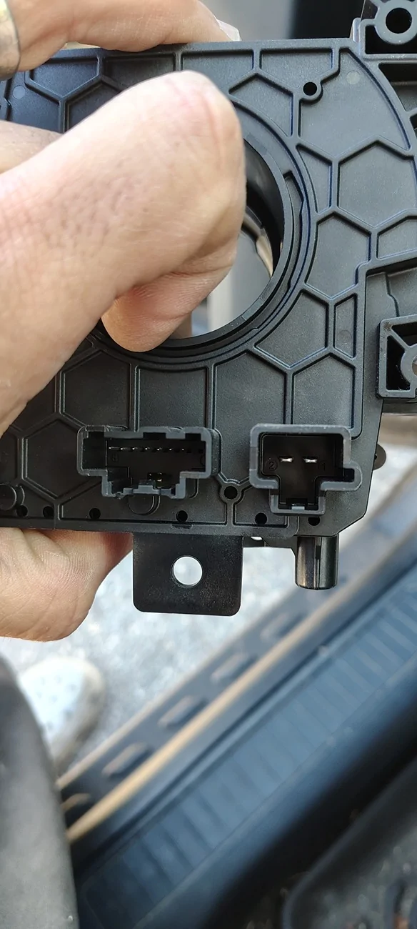
Above is the new to me sccm. It wasn't pinned by the salvage yard. But it's 3 full turns plus some in each direction for centering it. The new harness you've wired goes in the back (last pic above). The steering wheel plugs into the front. (Which also means don't buy just the clock spring, you'll need the whole assembly; however I should double check my old one for the connector hopefully I remember and will update this).
SCCM part numbers
according to sources For a 2025 Ford Maverick, the Steering Column Control Module (SCCM) / Clockspring architecture changed slightly from the 2022–2024 models to support the refreshed interior and updated driver-assist features.
The base Ford engineering part group for the Maverick's SCCM housing and clock spring assembly is 3F791. For the 2025 mid-cycle refresh, Ford updated the prefix code to SZ6Z
as you can see mine is SZ6B and ends with CA despite everything saying need DA
Software:
Software side:
Now that you've installed the replacement SCCM go into FORscan.
Use easy mode to enable heated steering wheel in the HVAC and in IPC modules, (the plain language easy settings).
The heated steering wheel button should now appear! If your lucky it might even work.
But don't forget to check your as built SCCM data. Make sure all your buttons and everything still work.
The donor SCCM needed to be re-flashed back to my build. As the buttons and such did not work at first. Also for me it lists the right side buttons as unconfigured, but they all worked once I sorted the as built codes.
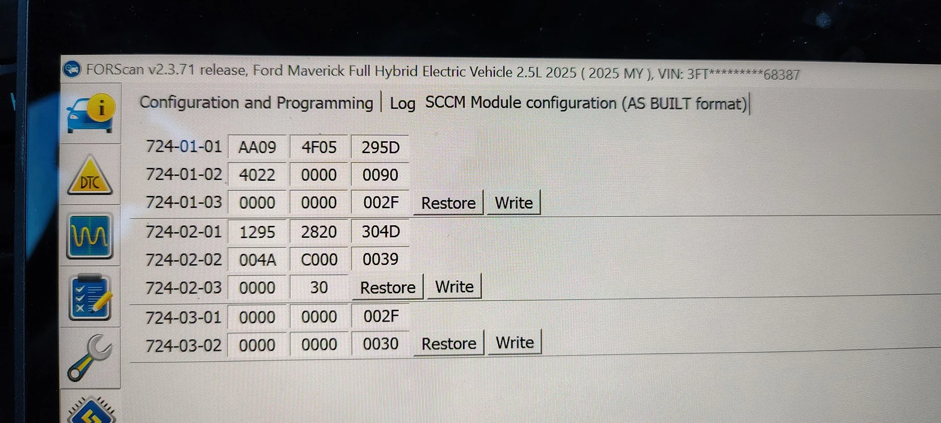
Above is my SCCM configuration.
But here's the kicker. I had the button. I had the power! But I didn't have the heat!!
There's one more programming language you have to do. Go into the HVAC as built codes
Change 733-01-04 the second set of numbers, fourth integer (4)
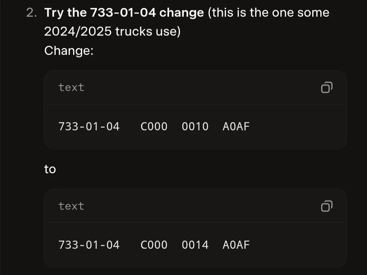
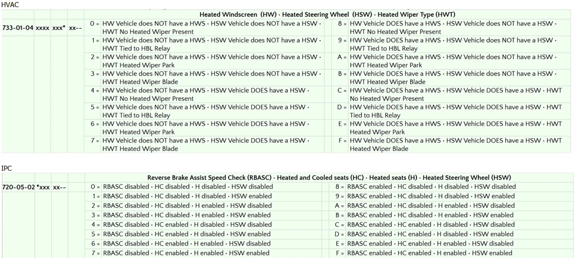
Because I don't have a heated windshield and I dont have heated wipers; That fourth integer is a 4.
Save your forscan settings.
Congratulations!
Now press the button, the little orange line under it should light up and you should feel some nice warmth in your wheel.
*Disclaimer: I'm no expert!
I do recommend anyone doing the adaptive cruise control consider this option while setting that up.
I've also attached some other images for guidance.
Lastly For those without 360, this will probably still work for you as the heating controller is in the HVAC entirely.
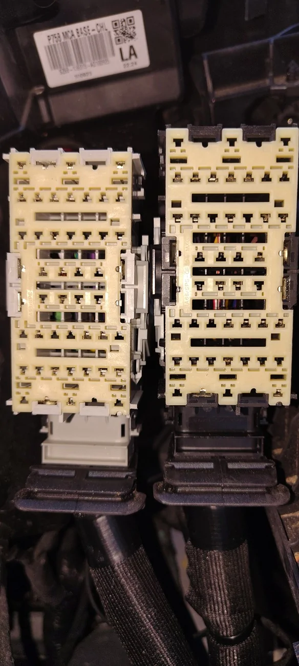
^both harnesses side by side the only outward differences ist he gray vs black plastics
this is where counting the pins and confirming everything should be done.

^note the second row of wires the empty slot, third from the right.
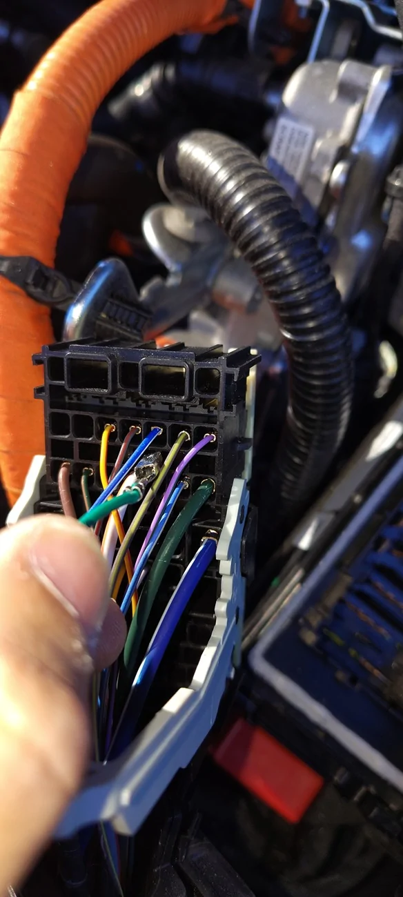
^ the orientation of the pin when you insert it into that empty slot.
So in this year B was on the right. But nonetheless on other years it's by the engine. Including 2025. So to be clear the harness by the engine is where you're going to be pushing that wire into.
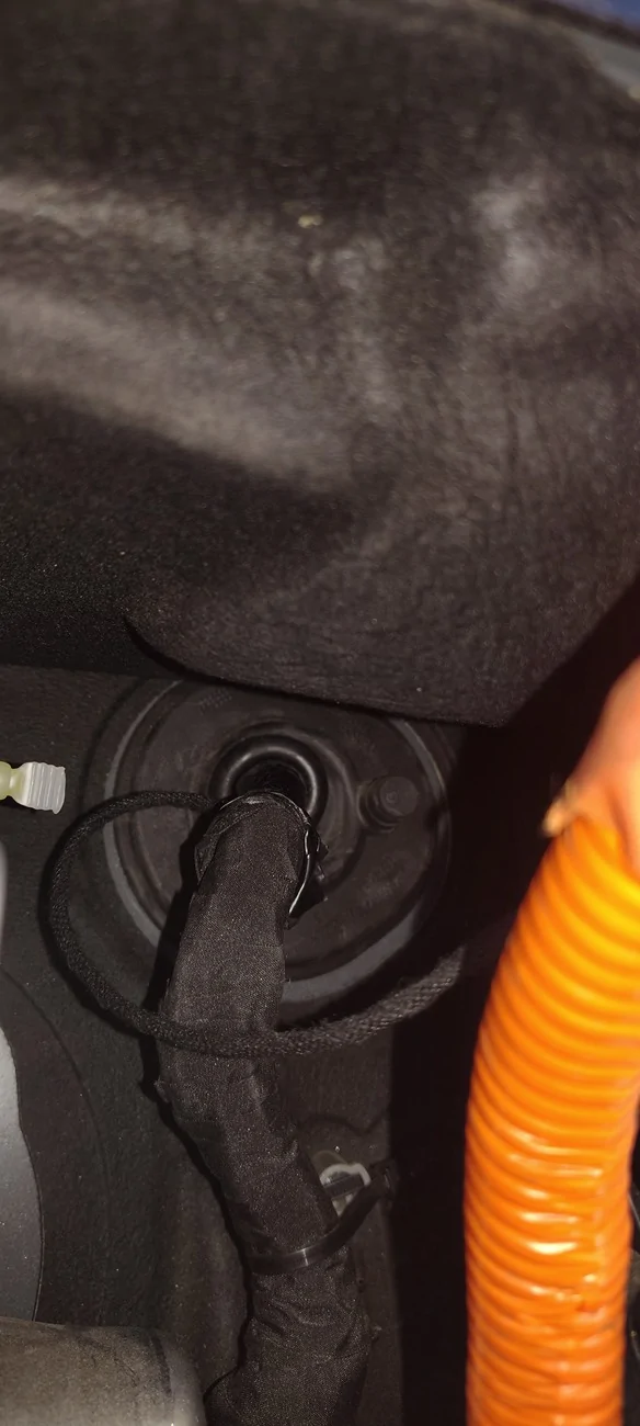
under the windshield wipers in the engine bay is the boot, you can see it is rolled back here for pushing the wire through. in the shadow next to the zip tie is the single layer rubber oval if you want to figure out an easier way. (its part number Jx6z-10A862-A)
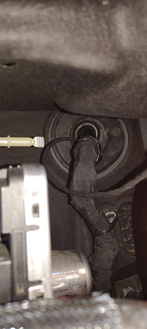
The wire coming through before resealing the grommet.
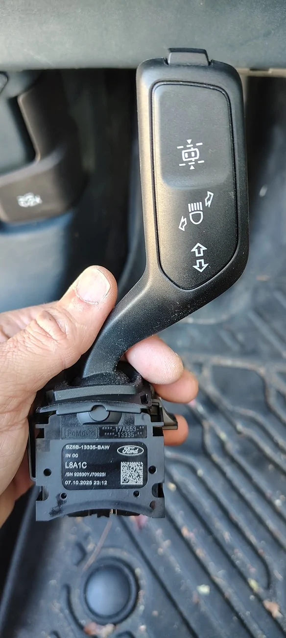
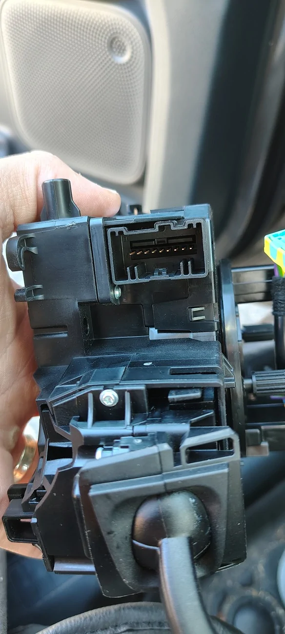
Left hand stalk with button
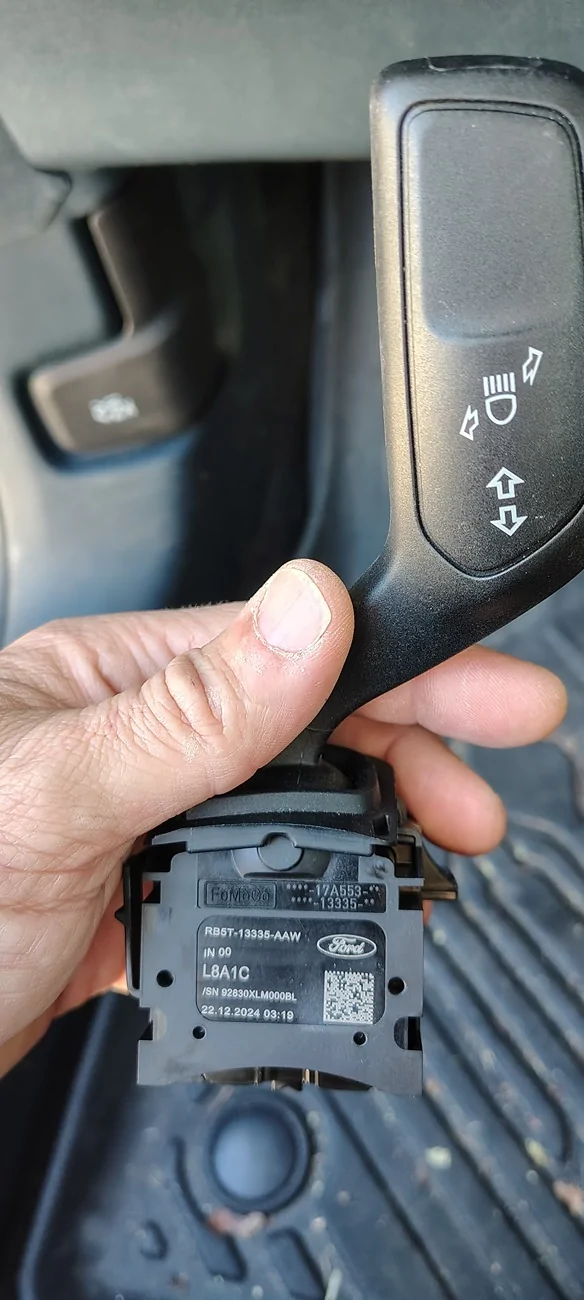
Left hand stalk without button.
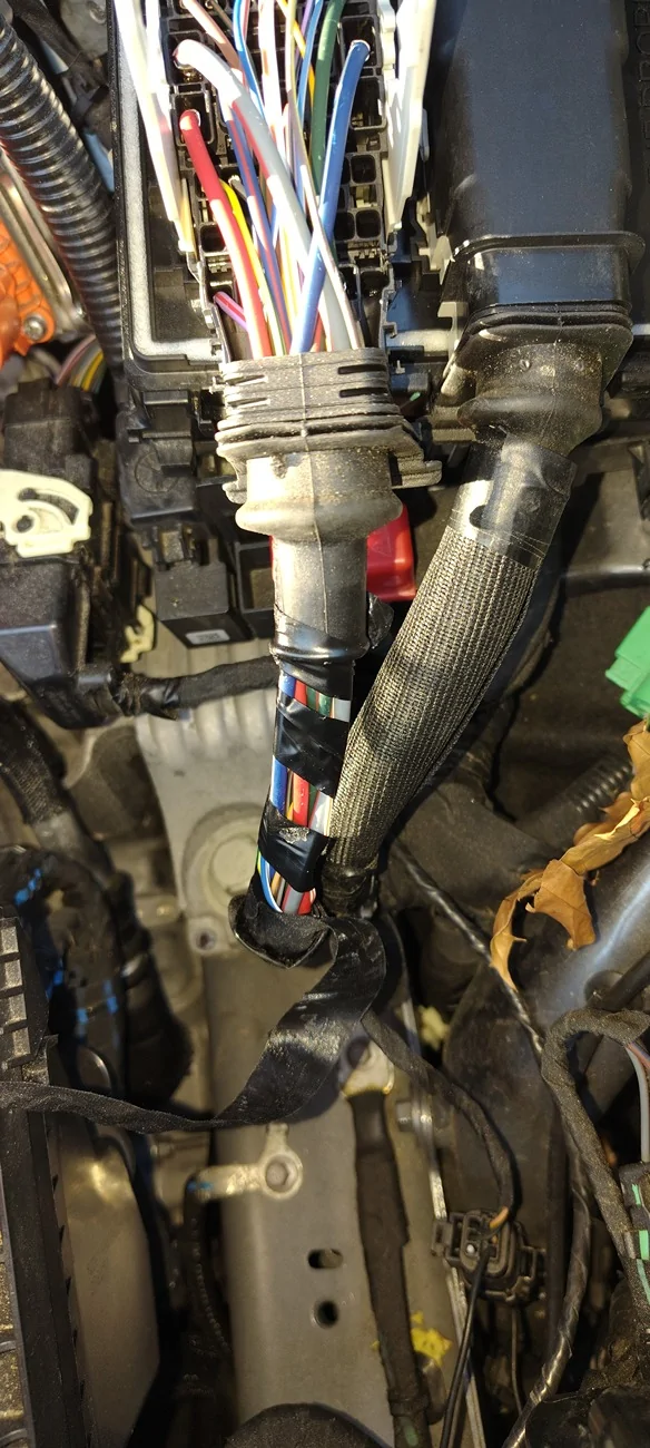
^ opened up the wires for feeding the power line .
Below is some pics of the done wiring. Hopefully they show it. Took some quick shots in the morning sun.
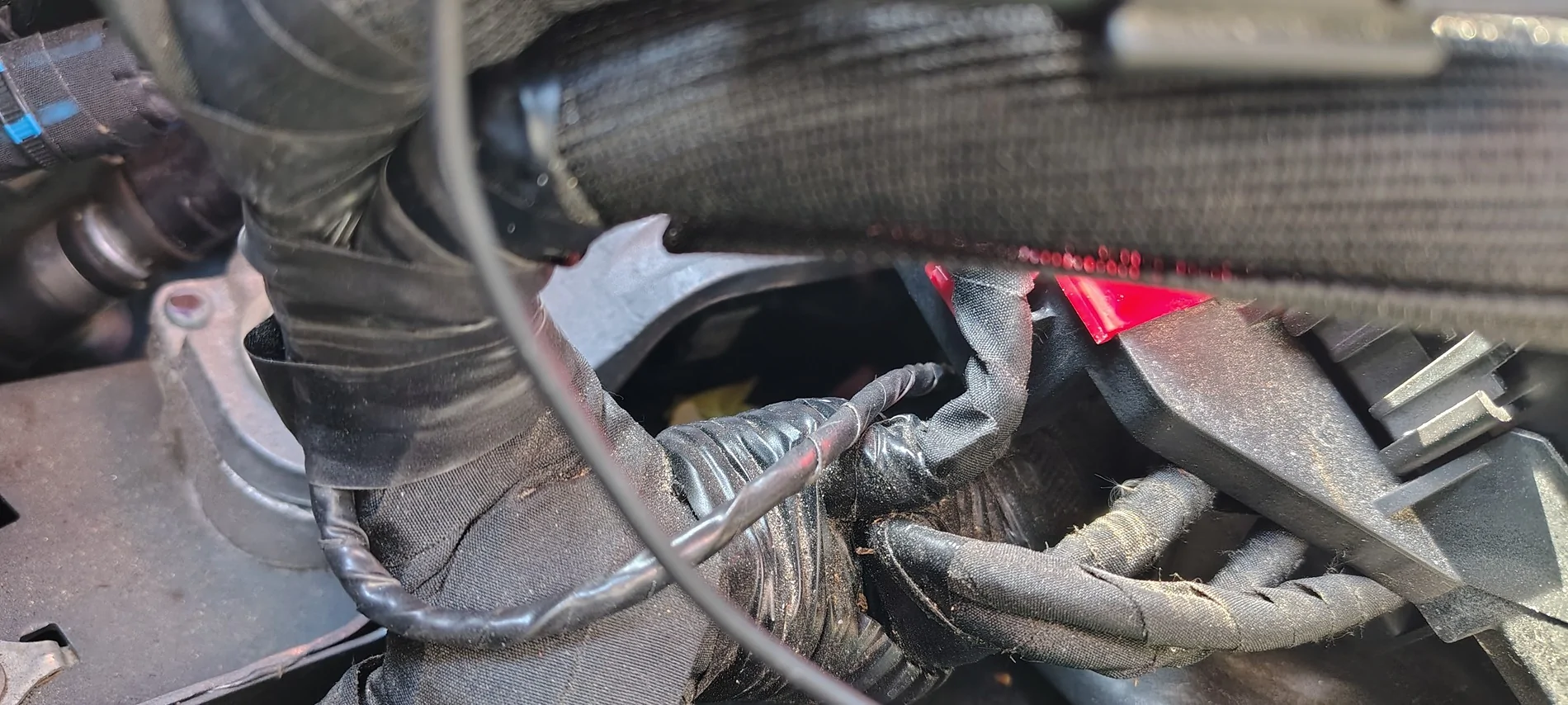
Taped back together the wire running out of the harness and then alongside it.
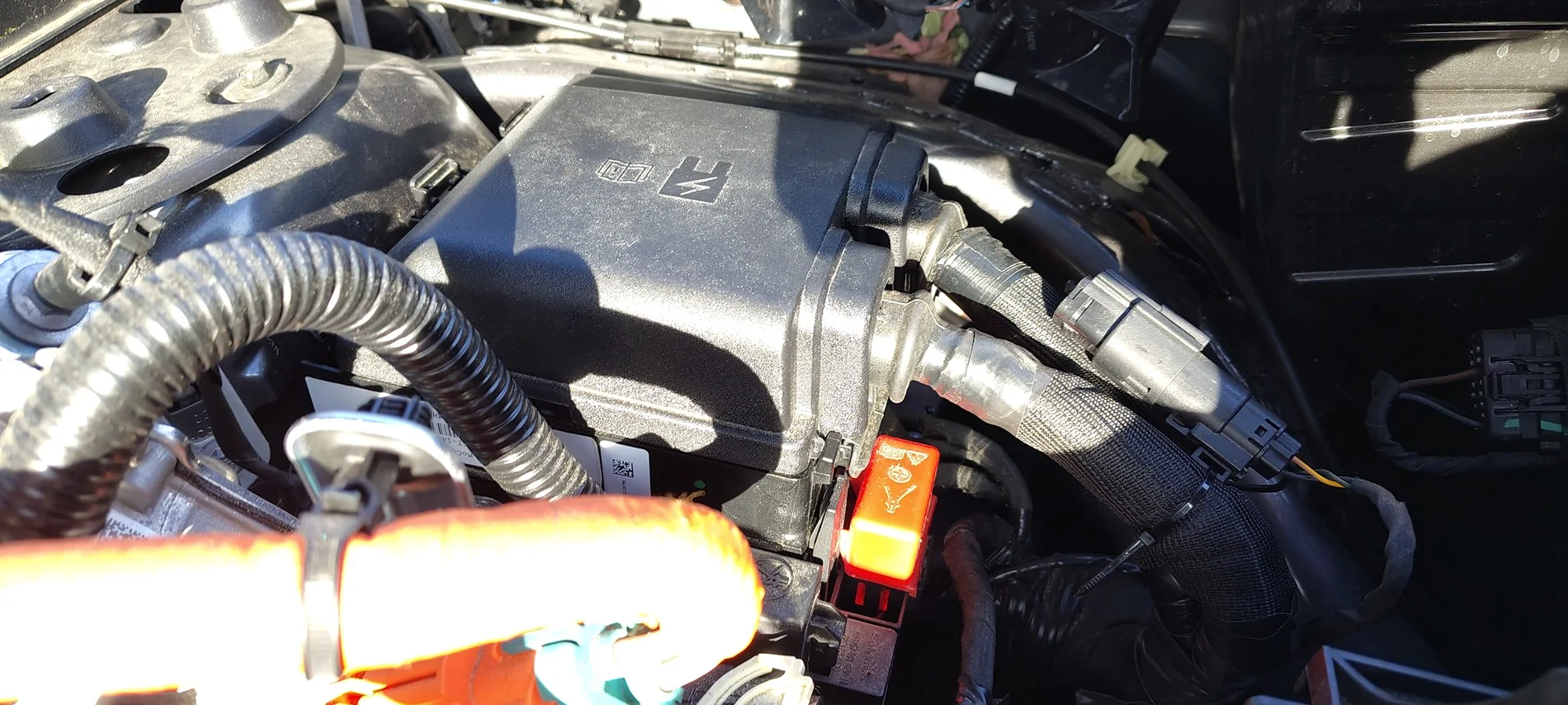
Reassembled
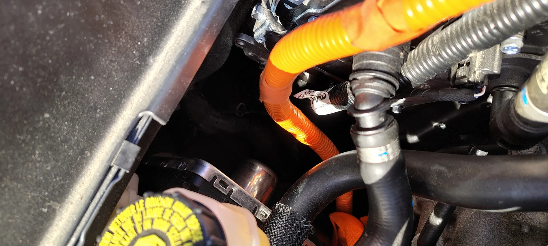
Where the wiring goes
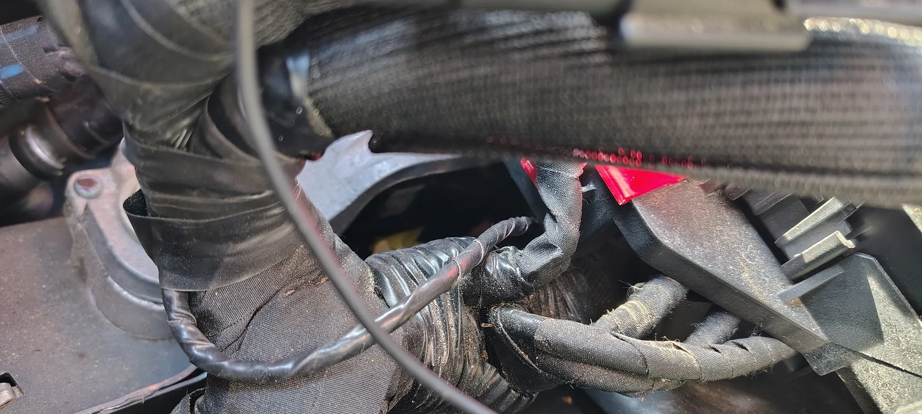
Here's how to enable heated steering in a 2025 XL.
First let me say thank you to all the members that supplied diagrams to me over the different threads (connectors, harnesses and codes).
Also thank you to the original poster for previous models- see his work here: https://www.mavericktruckclub.com/f...eated-steering-wheel-to-an-xl-maverick.39185/
QRD
1. need 12 volt power from an ignition switched source.
2. the matching connector to provide the power to the wheel ( WPT - 404 )
3. the matching hardware (heated wheel and steering control module SCCM).
4. Forscan settings in HVAC, SCCM and IPC.
* as the sync 4 system eliminated the physical hvac buttons you wont need anything else.
NEEDS
Compatible sccm (the ending suffix of the part numbers tells you... See more below)
wiring harness and 2.8 pin (see ebay listings)
A heated capable steering wheel.
And forscan.
I had previously purchased a heated wheel for the adaptive cruise control upgrade. The wheel came with the buttons for adaptive cruise at the same price as just buying the buttons.
For the sccm, search junkyards for totaled lariats. Then check eBay for the matching vin a lot of the times they aren't listing them by the part number, or even if it's heated steering! I paid 110 for the sccm.
Wiring:
On 2025 they did not include the wiring from the battery junction box to the cabin. You will need to run a wire from the engine fuse box into the cabin (Unless you got lucky or have a higher trim where the wire is present). In equipped models and previous years they used the c200 harness at the driver's footwell - the wire comes from the engine bay to the connector then to the steering wheel. So check your harnesses first for that yellow green wire.
*Also note just like with the battery junction box, Ford did do some flipping of placement of the c200 and c201(top or bottom harness). The related wiring diagrams are posted by members for me while I was researching this and can be found with the search function.
For the wiring I purchased off eBay "Ford F-150 2021-2026 Heated Steering Wheel Harness Kit Connector Retrofit US" (random listing in image↓)
^ as you can see it has the connector, ground connector and 2.8 pin already done for you.
Ok so here's how I did it. First identify fuse circuit 160 in the fuse box going to connector
C1035a (warning I found that Ford on different years changed the placements i.e. by the engine can be B or A).
There should be a fuse in place (15 amp)
You should be able to find a pin without the matching wiring in the connector for the harness (see pdfs for more detail) but you're looking for
CBBG0
(YE-GN) 18 FUSE - 160 OR CIRCUIT
BREAKER
Pin 34 (for 2025 it's in the one by the engine/ guessing it's always that side). *Every diagram I've seen per year does have it as pin 34 regardless of it being c1035A or c1035B. (Images just below my digression about wiring).
(^above photo of previous years wiring diagram. from the fuse box is CbbG0 and after the c200 harness it can be labeled CBB33 or remain CBBG0)
The pin: #34. Is a circuit that turns on with remote start and or the key.
Also of note the wheel draws 7.5 amps so the 15 amp circuit is more than enough and you could probably power a dash cam or something else with this.
There is an alternative passenger compartment fuse you can tap, but the micro3 taps suck.(I bought one off Amazon and the reviews are accurate you need a vice to press them in evenly and smoothly or it will break. The outer leg is in fact powered by both fuses, which is acceptable if you use that fuse slot as only of the two fuses on the micro3 is in fact in use).
First pic here is both sides of the battery junction box (fuse box). The left side is the engine side. When you look in you will see numbers stamped on the plastic for example 20 & 26. Those numbers are adjacent to that pin number to aid in counting and placement of the other pins.
Closer to the engine In my case (left side)
You'll slide that piece forward to insert the wire
^remember when looking at the pdf it's from the other side. From this view it's the third slot from the right. From the front of the harness it's the opposite.
It's push to click then reassemble the harness. (if you need a replacement harness because you really screwed up its connector "wire assembly WPT-1739")
Ok but what about the wire you say.
That eBay listing has the connector (2.8 sized already installed). I did wrap the whole engine side in electrical tape to cover the felt.
Now there's an access panel/grommet that you can use (big oval, but it won't seal) or fish it from the passenger compartment (driver's side) following the existing wiring harness. I used a reusable plastic straw to guide it through the rubber (rolled back the rubber onto it) (see the blue straw below)
Now I would have preferred coming from the engine side, because I ended up cutting the straw as it would have otherwise been on the wire forever. (you really only need a few inchs of the straw.)
Once you have the wire through retape everything so it's nice looking again. I followed the existing harness all the way to the fuse box. The rubber boot on the fuse box wasn't to tight and I was able to push that pinned end right through into the harness (pics further down).
The ground wire took me a few minutes to find. There is a good one behind the light switches
Ok now for remove your steering wheel, some people say disconnect your battery ground, I say disconnect your battery positive (everything is still grounded anyway) wait 15 minutes. Then turn wheel, push the buttons from the back side with your screwdriver to pop out the air bag. Use your 15/16 (double check this sizing) ratchet to remove the steering wheel bolt. Unplug the harnesses. Get to that sccm take the 4 bolts off. Remove and replace.
Before ordering a new module, you can check your truck's factory-installed clockspring. When you pull off the steering wheel shroud or look directly at the front face of your existing clockspring assembly:
- Check the small white or black multi-pin auxiliary connector slot that lines up with the steering wheel's heater plug. (see next picture below) If your factory unit is a lower-spec variant, you will notice the plastic slot is empty inside (no metal prongs/pins visible).
- If it contains the metal prongs, your truck was built with a compatible SCCM, and you only need to run the supplemental 12V power harness to the back of the module and program it via FORScan (maybe you even got extra lucky ands the harness is there in the back). * I should add a pic of the harness you can see it with the wheel assembled fully.
The new SCCM is below this first pic. First pic is the old one still in place.
^steering wheel side plug (maybe yours already came with the correct SCCM)
below are the part numbers
the new one backside the two prong harness is what you're looking for.
Above is the new to me sccm. It wasn't pinned by the salvage yard. But it's 3 full turns plus some in each direction for centering it. The new harness you've wired goes in the back (last pic above). The steering wheel plugs into the front. (Which also means don't buy just the clock spring, you'll need the whole assembly; however I should double check my old one for the connector hopefully I remember and will update this).
SCCM part numbers
according to sources For a 2025 Ford Maverick, the Steering Column Control Module (SCCM) / Clockspring architecture changed slightly from the 2022–2024 models to support the refreshed interior and updated driver-assist features.
The base Ford engineering part group for the Maverick's SCCM housing and clock spring assembly is 3F791. For the 2025 mid-cycle refresh, Ford updated the prefix code to SZ6Z
as you can see mine is SZ6B and ends with CA despite everything saying need DA
Software:
Software side:
Now that you've installed the replacement SCCM go into FORscan.
Use easy mode to enable heated steering wheel in the HVAC and in IPC modules, (the plain language easy settings).
The heated steering wheel button should now appear! If your lucky it might even work.
But don't forget to check your as built SCCM data. Make sure all your buttons and everything still work.
The donor SCCM needed to be re-flashed back to my build. As the buttons and such did not work at first. Also for me it lists the right side buttons as unconfigured, but they all worked once I sorted the as built codes.
Above is my SCCM configuration.
But here's the kicker. I had the button. I had the power! But I didn't have the heat!!
There's one more programming language you have to do. Go into the HVAC as built codes
Change 733-01-04 the second set of numbers, fourth integer (4)
Because I don't have a heated windshield and I dont have heated wipers; That fourth integer is a 4.
Save your forscan settings.
Congratulations!
Now press the button, the little orange line under it should light up and you should feel some nice warmth in your wheel.
*Disclaimer: I'm no expert!
I do recommend anyone doing the adaptive cruise control consider this option while setting that up.
I've also attached some other images for guidance.
Lastly For those without 360, this will probably still work for you as the heating controller is in the HVAC entirely.
^both harnesses side by side the only outward differences ist he gray vs black plastics
this is where counting the pins and confirming everything should be done.
^note the second row of wires the empty slot, third from the right.
^ the orientation of the pin when you insert it into that empty slot.
So in this year B was on the right. But nonetheless on other years it's by the engine. Including 2025. So to be clear the harness by the engine is where you're going to be pushing that wire into.
under the windshield wipers in the engine bay is the boot, you can see it is rolled back here for pushing the wire through. in the shadow next to the zip tie is the single layer rubber oval if you want to figure out an easier way. (its part number Jx6z-10A862-A)
The wire coming through before resealing the grommet.
Left hand stalk with button
Left hand stalk without button.
^ opened up the wires for feeding the power line .
Below is some pics of the done wiring. Hopefully they show it. Took some quick shots in the morning sun.
Taped back together the wire running out of the harness and then alongside it.
Reassembled
Where the wiring goes
Sponsored
Attachments
-
166.3 KB Views: 3
-
361.7 KB Views: 4
Last edited: