

- First Name
- Jose
- Joined
- Oct 23, 2024
- Threads
- 8
- Messages
- 30
- Reaction score
- 60
- Location
- New Braunfels, Tx
- Vehicle(s)
- 2024 Ford Maverick Hybrid Lariat
- Engine
- 2.5L Hybrid
- Thread starter
- #1
This is the fifth of five long posts; on the B&O sound system upgrade of my 2024 Ford Maverick with Lariat trim. Here are the titles of the 5 posts:
Part 1: Introduction and Conclusion of B&O Sound System Upgrade
Part 2: B&O Front Door, Tweeter and Rear Speaker Replacement
Part 3: B&O Center Speaker Replacement with a 4 inch Speaker
Part 4: B&O Subwoofer Replacement
Part 5: B&O Upgrade, Subwoofer Amp Installation
Components for Subwoofer Amp Installation:
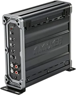
- KICKER 46CXA4001T CXA400.1 400w Mono Class D Car Audio Amplifier Amp
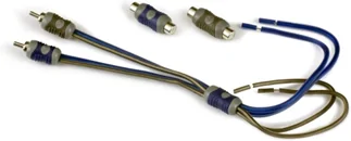
- KICKER 46KISL K-Series Interconnect, Speaker Wire to RCA Adapter
- RD Rock Direct True Spec 8 Gauge Car Audio Cable Amp Wiring Kit - 2 Channel CCA Power Cable Amplifier Install Wiring Kit with Tinned OFC RCA Cable (not pictured)
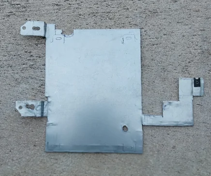
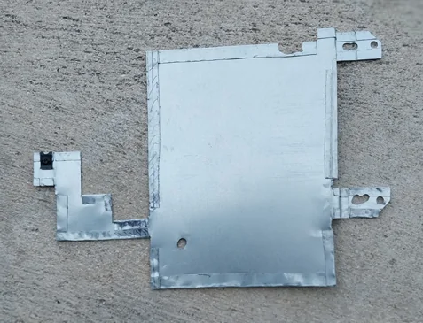
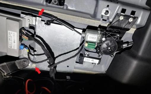
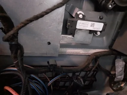
Only the 3 ground wires are mounted directly to the back wall of the cab. My truck is a hybrid so the battery is under the back seat and may have additional ground point connections. The amp, antenna module, back window module, wiring are all mounted on brackets which extend from the back of the cab. Wiring is also elevated from the floor of the cab. Noting this I decided to make a mounting plate to keep the amp off the floor and back wall of the cab. The mounting plate attaches to OEM amp mounting points and behind an existing hole in the antenna module mounting bracket. You can see the speed nut I used to make the attachment point behind the antenna module. The mounting plate is made of galvanized steel and was cut using a Dremel. I made double back bends on the plate for rigidity. I started with a piece of cardboard, transposed the templated on to the steel plate and carefully cut and bent. There were many test fits until I got what I wanted. The plate has two ¼” bends by the OEM amp mounting points. These bends make the plate evenly spaced from the back of the cab. The antenna module mounting point is closer to the back of the cab than the amp. The notch on the top of plate is necessary to clear a hold for the rear window actuator. The hole on bottom of the plate is not necessary. I one point I thought I would need it. I had to use a rat tail file, to elongate the hole, to get the correct position of the mounting holes at the OEM amp. There is an unnecessary hole at both amp mounting points.
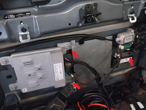
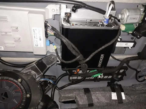
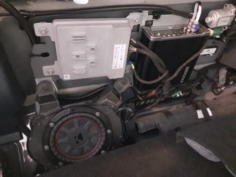
Some photos of the final installation. The large green connector just below the “KICKER” label of the amp is the OEM subwoofer input connection. It connects to the repurposed OEM subwoofer harness which was cut and soldered to the KICKER 46KISL K-Series Interconnect, Speaker Wire to RCA Adapter. I soldered the single subwoofer harness to both KICKER 46KISL K-Series wires. The green wire on the OEM subwoofer harness is positive (+). The center pin on the RCA connector is positive (+). This harness is routed behind the mounting plate in convoluted tubing.
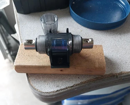
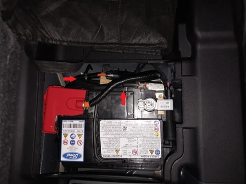
The low power rating of the amp only requires 8 gauge power wires. Connecting the 12V source to the amp is not my best work. There was no real space to place and attach the in line fuse, that remains accessible, without removing additional plastic panels. I screwed the inline fuse into a block of wood so it would safely sit on top the battery ground wiring, which attaches to the floor of the cab. The positive wire is in convoluted tubing to provide protection against chaffing. The screw bolt which holds the battery terminal to the battery does not screw off. This required I cut some “O” ring power connector to make fork connection. That way I could slide and cinch the 12 V positive power line to battery terminal. Used plastic ties to hold positive 12V cable in place. One tie is at the bottom of battery and second is at the top. Both attach to the negative power line. As I said not my best work… From the battery the positive cable, in convoluted tubing, follows OEM wiring routing and exits by a spot, on the floor of the cab near rear passenger door. I then ran the positive cable over the primary support bracket of the back seat. The positive cable is loosely held in place by a plastic tie. The ground wire for the amp is routed between the OEM amp and subwoofer enclosure. It attaches to the ground point connection by the rear passenger door on the back of the cab. I did not connect the remote turn-on. The Amp powers up when a door of the truck is opened. I have observed the amp to itself off with the sound system off and a door open.
Amp Setup
The KICKER 48CWRT672 is spec’d to have a frequency response of 30 Hz to 500 Hz. With the 4” rear speakers, the truck needs the added bass from the subwoofer. Being a smaller subwoofer and needing bass from the back of the truck, I set the crossover of the Amp to 200 Hz. If the truck had larger rear speakers I would set the crossover to 80 Hz. To establish the volume of the subwoofer, I first set the input gain of the amp and bass boost to its lowest setting. Next I power on the sound system, play some favorite music, with bass, and set the volume very high, below the point the system clips. Next I increase the input gain on the amp until the subwoofer is too loud. Now I lower the volume of the sound system to a comfortable but still loud volume. I adjusted the input gain of the amp and bass boost to my taste. Surprisingly, the subwoofer bass is not compromised with the seat back up. The bass emanates from rear and not just from the subwoofer location. A couple of days later, after driving with the normal volume, I made, my last, the input gain and bass boost adjustments.
Part 1: Introduction and Conclusion of B&O Sound System Upgrade
Part 2: B&O Front Door, Tweeter and Rear Speaker Replacement
Part 3: B&O Center Speaker Replacement with a 4 inch Speaker
Part 4: B&O Subwoofer Replacement
Part 5: B&O Upgrade, Subwoofer Amp Installation
Components for Subwoofer Amp Installation:
- KICKER 46CXA4001T CXA400.1 400w Mono Class D Car Audio Amplifier Amp
- KICKER 46KISL K-Series Interconnect, Speaker Wire to RCA Adapter
- RD Rock Direct True Spec 8 Gauge Car Audio Cable Amp Wiring Kit - 2 Channel CCA Power Cable Amplifier Install Wiring Kit with Tinned OFC RCA Cable (not pictured)
Only the 3 ground wires are mounted directly to the back wall of the cab. My truck is a hybrid so the battery is under the back seat and may have additional ground point connections. The amp, antenna module, back window module, wiring are all mounted on brackets which extend from the back of the cab. Wiring is also elevated from the floor of the cab. Noting this I decided to make a mounting plate to keep the amp off the floor and back wall of the cab. The mounting plate attaches to OEM amp mounting points and behind an existing hole in the antenna module mounting bracket. You can see the speed nut I used to make the attachment point behind the antenna module. The mounting plate is made of galvanized steel and was cut using a Dremel. I made double back bends on the plate for rigidity. I started with a piece of cardboard, transposed the templated on to the steel plate and carefully cut and bent. There were many test fits until I got what I wanted. The plate has two ¼” bends by the OEM amp mounting points. These bends make the plate evenly spaced from the back of the cab. The antenna module mounting point is closer to the back of the cab than the amp. The notch on the top of plate is necessary to clear a hold for the rear window actuator. The hole on bottom of the plate is not necessary. I one point I thought I would need it. I had to use a rat tail file, to elongate the hole, to get the correct position of the mounting holes at the OEM amp. There is an unnecessary hole at both amp mounting points.
Some photos of the final installation. The large green connector just below the “KICKER” label of the amp is the OEM subwoofer input connection. It connects to the repurposed OEM subwoofer harness which was cut and soldered to the KICKER 46KISL K-Series Interconnect, Speaker Wire to RCA Adapter. I soldered the single subwoofer harness to both KICKER 46KISL K-Series wires. The green wire on the OEM subwoofer harness is positive (+). The center pin on the RCA connector is positive (+). This harness is routed behind the mounting plate in convoluted tubing.
The low power rating of the amp only requires 8 gauge power wires. Connecting the 12V source to the amp is not my best work. There was no real space to place and attach the in line fuse, that remains accessible, without removing additional plastic panels. I screwed the inline fuse into a block of wood so it would safely sit on top the battery ground wiring, which attaches to the floor of the cab. The positive wire is in convoluted tubing to provide protection against chaffing. The screw bolt which holds the battery terminal to the battery does not screw off. This required I cut some “O” ring power connector to make fork connection. That way I could slide and cinch the 12 V positive power line to battery terminal. Used plastic ties to hold positive 12V cable in place. One tie is at the bottom of battery and second is at the top. Both attach to the negative power line. As I said not my best work… From the battery the positive cable, in convoluted tubing, follows OEM wiring routing and exits by a spot, on the floor of the cab near rear passenger door. I then ran the positive cable over the primary support bracket of the back seat. The positive cable is loosely held in place by a plastic tie. The ground wire for the amp is routed between the OEM amp and subwoofer enclosure. It attaches to the ground point connection by the rear passenger door on the back of the cab. I did not connect the remote turn-on. The Amp powers up when a door of the truck is opened. I have observed the amp to itself off with the sound system off and a door open.
Amp Setup
The KICKER 48CWRT672 is spec’d to have a frequency response of 30 Hz to 500 Hz. With the 4” rear speakers, the truck needs the added bass from the subwoofer. Being a smaller subwoofer and needing bass from the back of the truck, I set the crossover of the Amp to 200 Hz. If the truck had larger rear speakers I would set the crossover to 80 Hz. To establish the volume of the subwoofer, I first set the input gain of the amp and bass boost to its lowest setting. Next I power on the sound system, play some favorite music, with bass, and set the volume very high, below the point the system clips. Next I increase the input gain on the amp until the subwoofer is too loud. Now I lower the volume of the sound system to a comfortable but still loud volume. I adjusted the input gain of the amp and bass boost to my taste. Surprisingly, the subwoofer bass is not compromised with the seat back up. The bass emanates from rear and not just from the subwoofer location. A couple of days later, after driving with the normal volume, I made, my last, the input gain and bass boost adjustments.
Sponsored


