
- First Name
- Tom
- Joined
- Apr 16, 2024
- Threads
- 7
- Messages
- 115
- Reaction score
- 99
- Location
- Stuttgart, Germany
- Vehicle(s)
- 2021 C8, 2016 HellCat, 2014 Nissan Frontier-V8
- Engine
- 2.0L EcoBoost
- Thread starter
- #16
So... Myself and a buddy of mine have been working on this for a little bit and have a couple things to share and some questions for the community.
First, we don't see how Ivan was able to fit this without grinding a good bit off the spindle's caliper mounting perches. As you'll see in the photos, in order to bring the caliper down closer to the hub, a fair bit of grinding will be needed. I personally think it's acceptable, my buddy doesn't necessarily agree.
What are your thoughts?
Second, since i've already invested in the rotors and calipers, I want to go ahead and work through this and use these parts. My buddy is working on the next version of the adapter but we're also looking for a used spindle/knuckle to use for mock up and grinding on and it hasn't been easy, if you guys can point me in a good direction, that would be helpful. RockAuto does not show these parts on their site.
Lastly, if we get this adapter worked out AND it doesn't seem to negatively affect the integrity of the spindle, would anyone else be interested in this as a low volume product? My buddy can make the prototypes on his lathe and depending on the interest, maybe a few sets from time to time. We haven't even looked at how much it would cost to have a machine shop make these for us. If there are more than just a couple folks interested, we may go down that road. I'm NOT looking to going into business with this. Besides, how would I protect myself in case you screwed something up on your end?
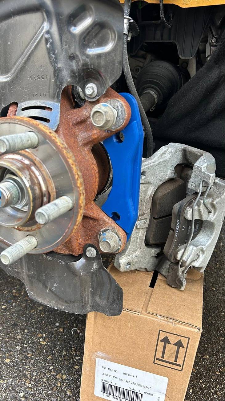
Anyways, on to the pics. So far we've just 3d printed the adapters and the appropriate brake pads for mock up.
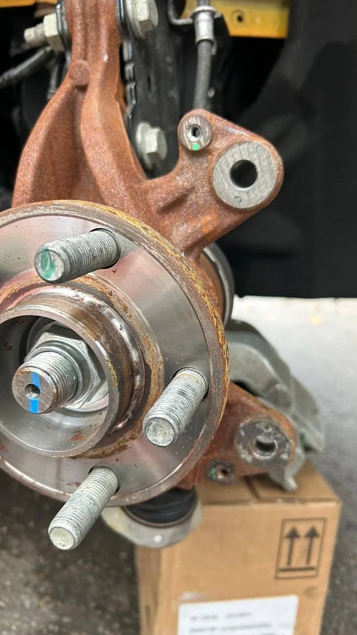
You can see in this photo that to move the caliper closer to the center of the hub, you have to move those inner holes on the adapter lower and to do that, you have to do some griding to those mounting ears. it needs to go down about 1cm.
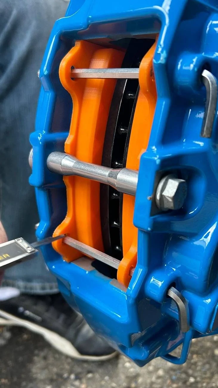
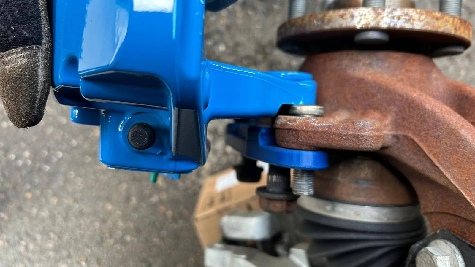
This photo and the next shows how high the caliper sits on the rotor.
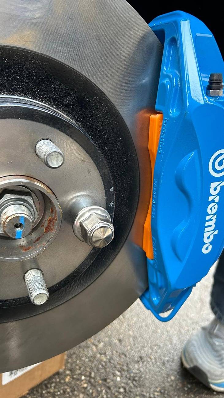
As you can see here, the caliper needs to move down about 1cm.
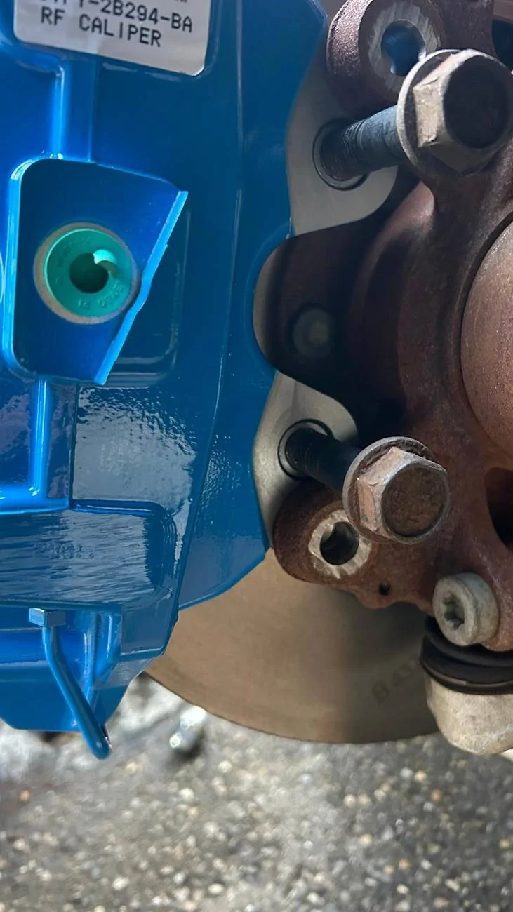
You can see here just how much material is on those ears but even so, my buddy is apprehensive about grinding on them to make this work.
This shows that you'd have to press some kind of stud into the spindle to be able to clear the caliper. We ground down a subaru wheel stud(it's what we had that fit) and even then, it's a tight fit.
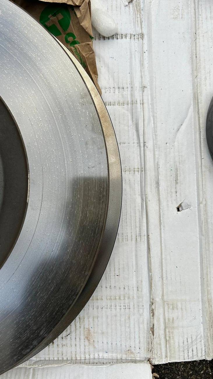
This shows the difference in the rotors. The Focus rotors have a larger diameter but the Maverick rotors are quite a bit thicker, I didn't take a photo showing that difference.
First, we don't see how Ivan was able to fit this without grinding a good bit off the spindle's caliper mounting perches. As you'll see in the photos, in order to bring the caliper down closer to the hub, a fair bit of grinding will be needed. I personally think it's acceptable, my buddy doesn't necessarily agree.
What are your thoughts?
Second, since i've already invested in the rotors and calipers, I want to go ahead and work through this and use these parts. My buddy is working on the next version of the adapter but we're also looking for a used spindle/knuckle to use for mock up and grinding on and it hasn't been easy, if you guys can point me in a good direction, that would be helpful. RockAuto does not show these parts on their site.
Lastly, if we get this adapter worked out AND it doesn't seem to negatively affect the integrity of the spindle, would anyone else be interested in this as a low volume product? My buddy can make the prototypes on his lathe and depending on the interest, maybe a few sets from time to time. We haven't even looked at how much it would cost to have a machine shop make these for us. If there are more than just a couple folks interested, we may go down that road. I'm NOT looking to going into business with this. Besides, how would I protect myself in case you screwed something up on your end?
Anyways, on to the pics. So far we've just 3d printed the adapters and the appropriate brake pads for mock up.
You can see in this photo that to move the caliper closer to the center of the hub, you have to move those inner holes on the adapter lower and to do that, you have to do some griding to those mounting ears. it needs to go down about 1cm.
This photo and the next shows how high the caliper sits on the rotor.
As you can see here, the caliper needs to move down about 1cm.
You can see here just how much material is on those ears but even so, my buddy is apprehensive about grinding on them to make this work.
This shows that you'd have to press some kind of stud into the spindle to be able to clear the caliper. We ground down a subaru wheel stud(it's what we had that fit) and even then, it's a tight fit.
This shows the difference in the rotors. The Focus rotors have a larger diameter but the Maverick rotors are quite a bit thicker, I didn't take a photo showing that difference.
Sponsored
Last edited: