- Thread starter
- #1
@blackb13 made a post about using Ada 1626 LEDs for ambient lighting. I bought some and noticed while playing around with them that they are very fragile, so elected to construct a housing for them.
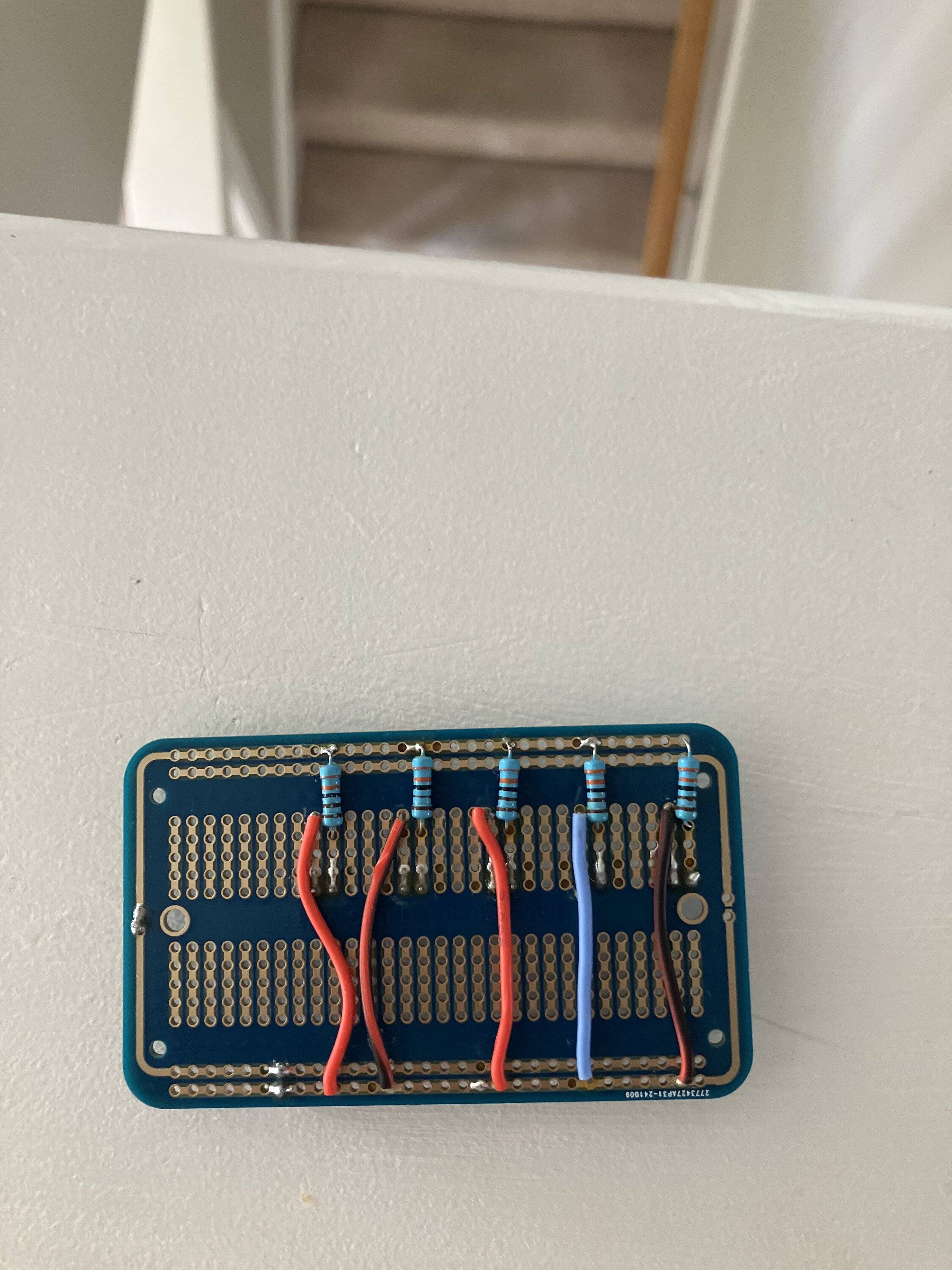
While doing so I also wanted my ambient lighting to be easily modified, so I created a "power block" out of a permaboard and mounted the resistors (I went with 3.3k to keep light output down a little) to it, and put it in a housing, using JST connectors to wire up each light. This allows them to be replaced/expanded easily and/or replace the board with a potentiometer to adjust brightness when I get around to adding that.
I used "clear" PLA filament when printing, it's not clear but clear enough for light transmittal:
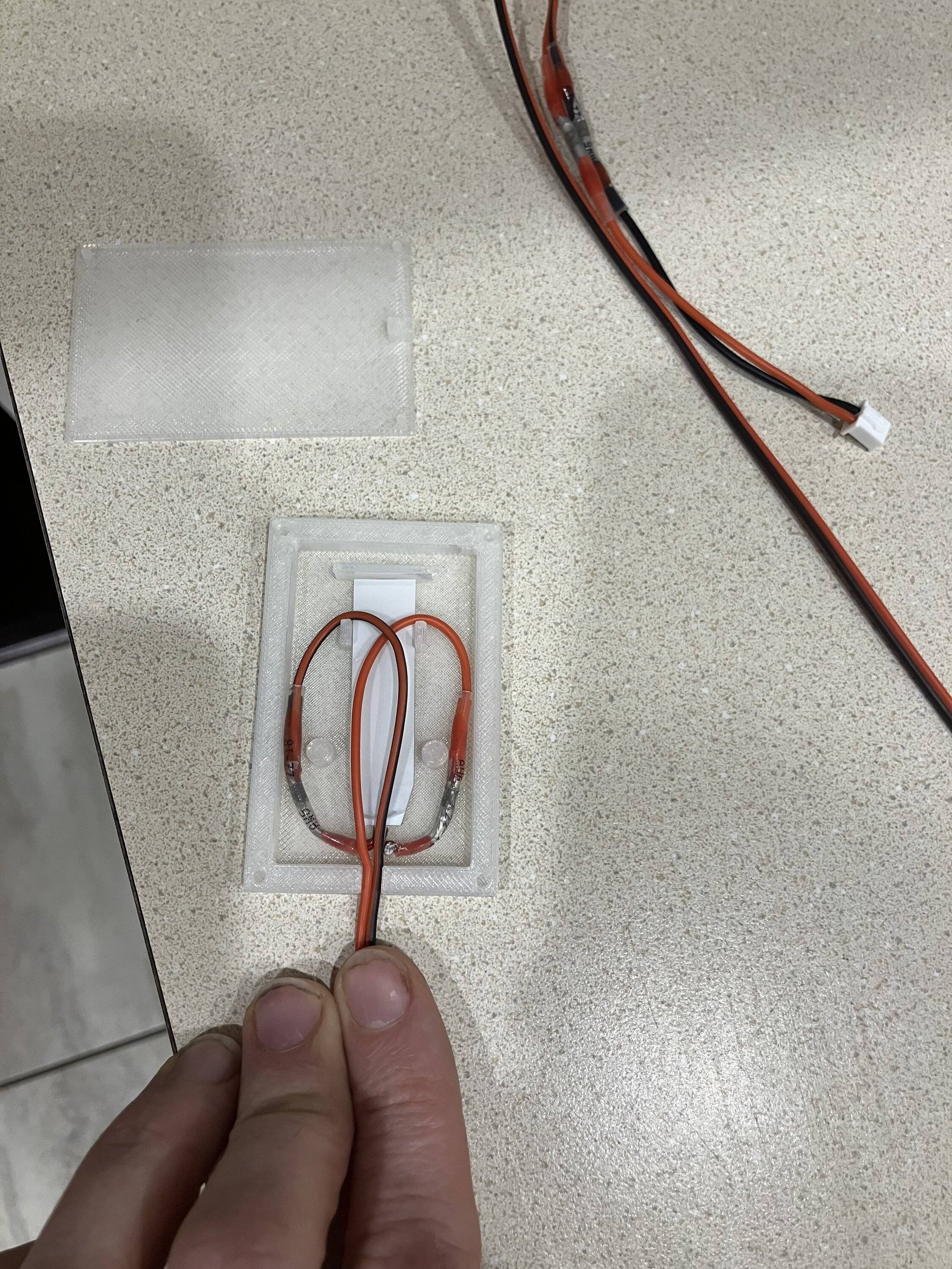
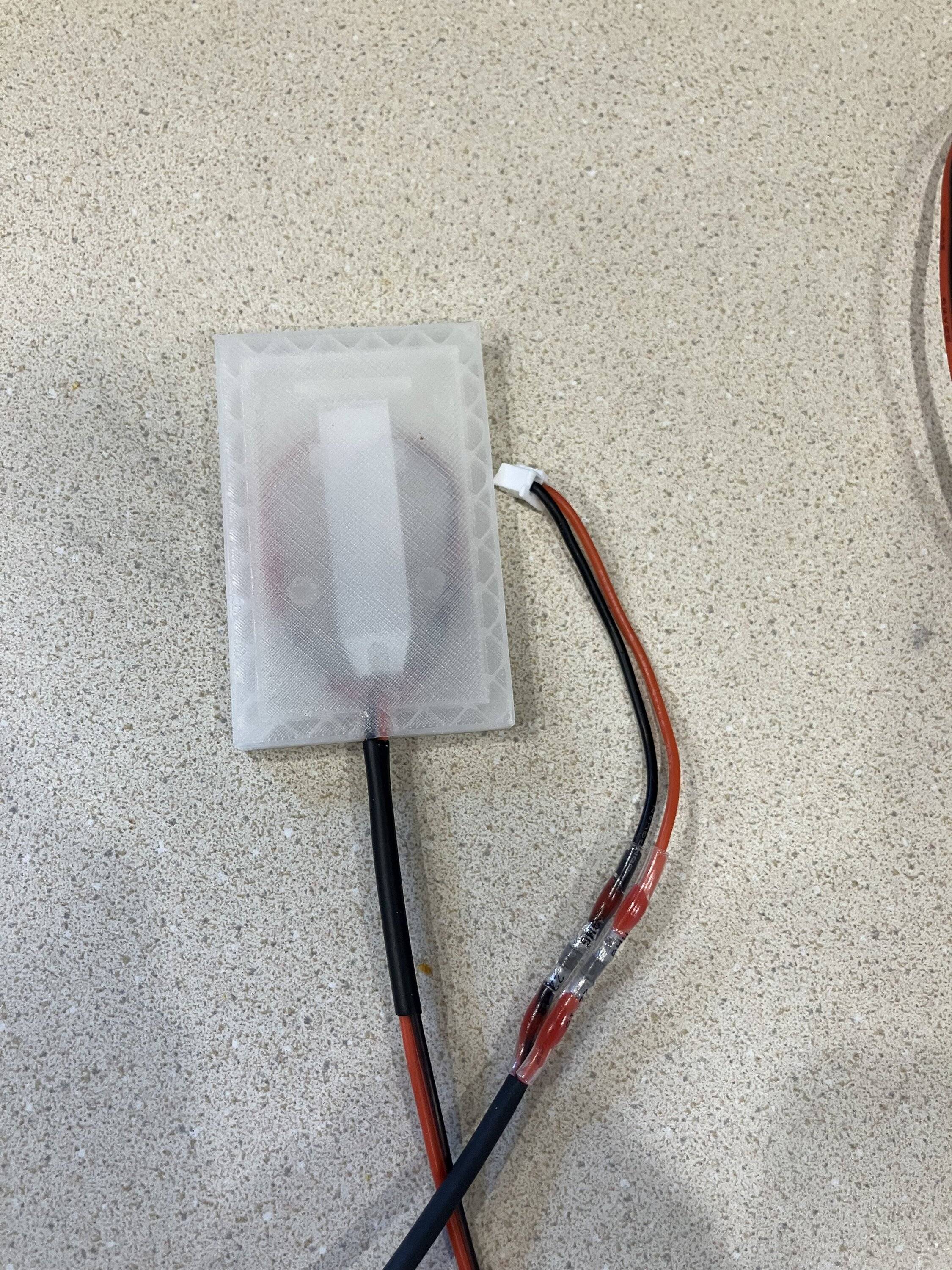
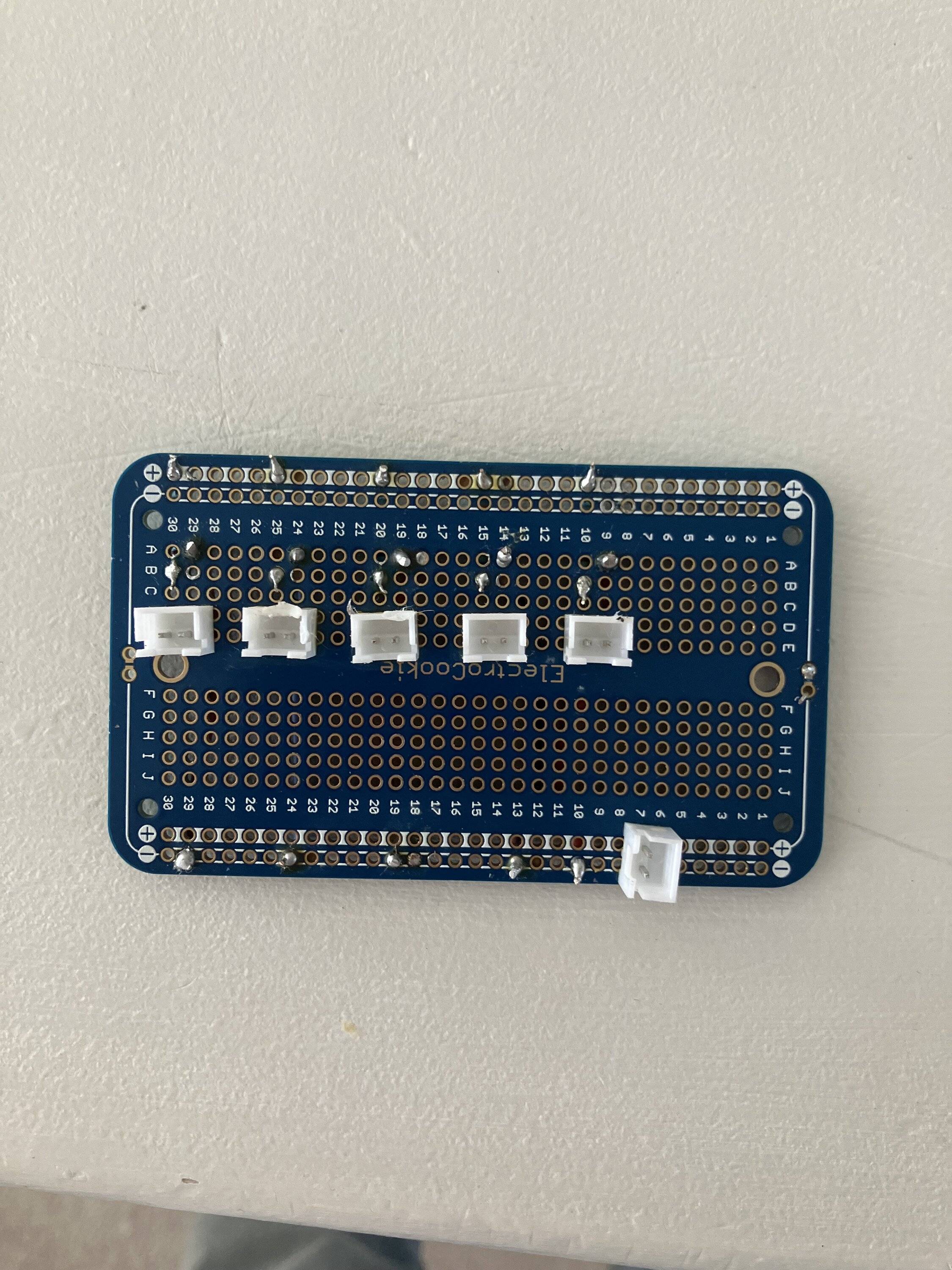
Using a Permaboard breadboard I soldered in JST connectors to allow easy plug-in access for the power (bottom right) and up to five LEDs. After extensive testing in my garage I ended up with 3.3k resistors as I found those offered the best light output levels, with lower resistance making it too bright for my tastes (YMMV). I placed the board in a box I also 3D printed. I'd like to replace the high resistors with a potentiometer or similar in a future version so that I can adjust them to my desired output dynamically.

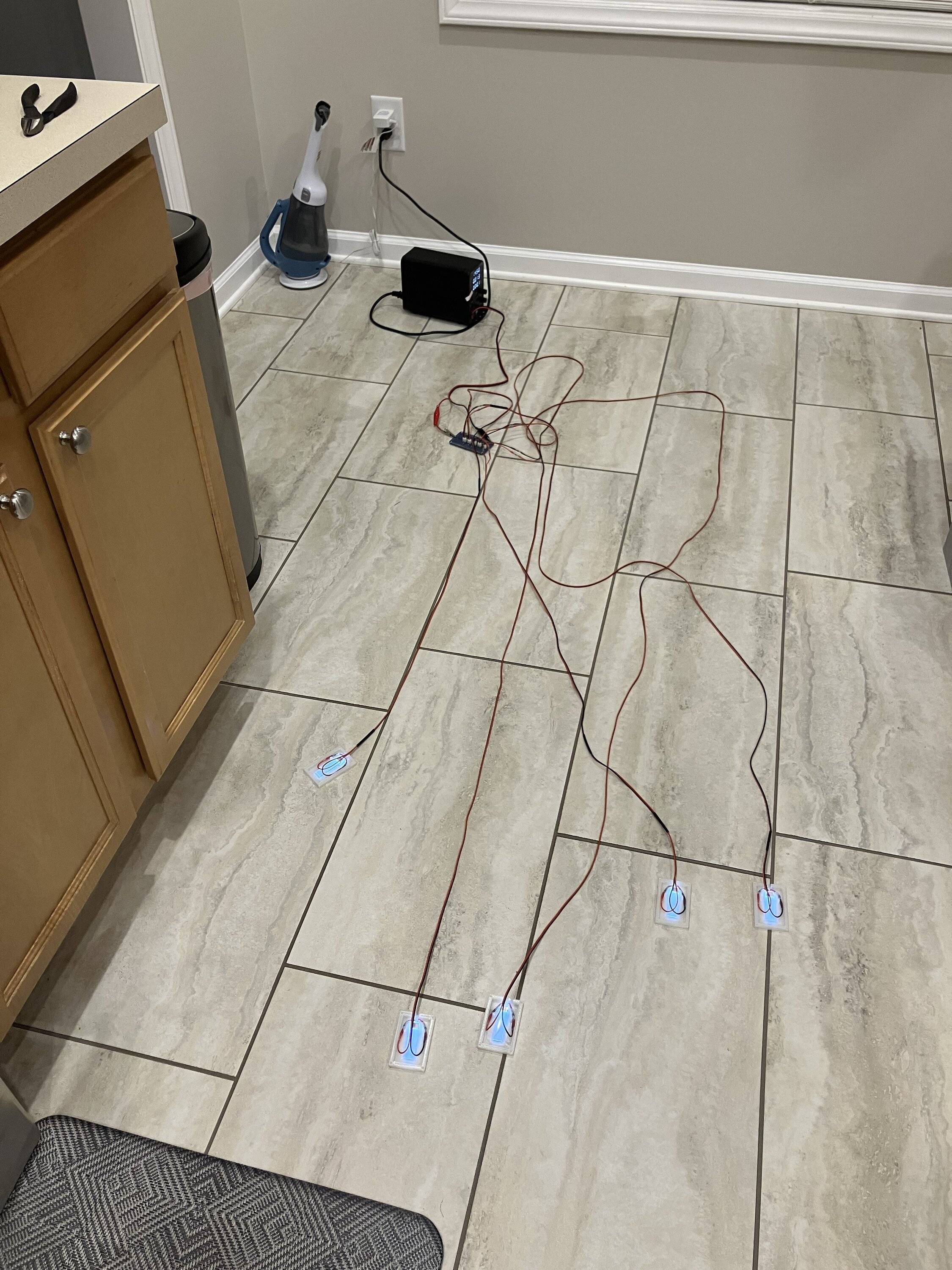
Testing them with a power supply set to 14.5v shows how they are designed to work, using plug 'n play power so you can just plug in ones as you expand or replace the ones that go bad with another easily. Being LED and using very low output (roughly 3 mAh IIRC) they should last a very long time. I used a fuse tap and tapped into a new circuit to power the box, but they will draw very, very little power combined, about 1/7 of an amp.
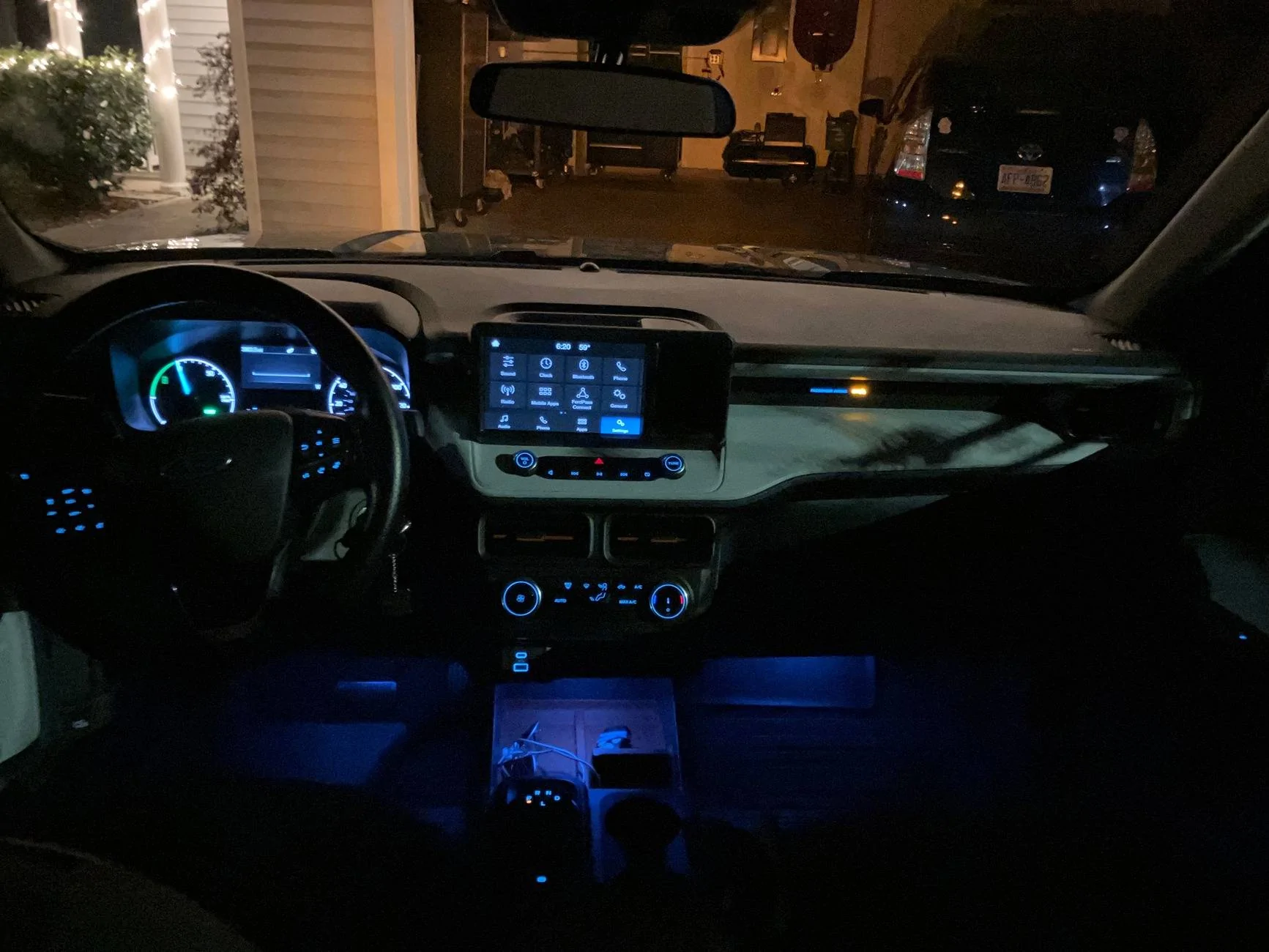
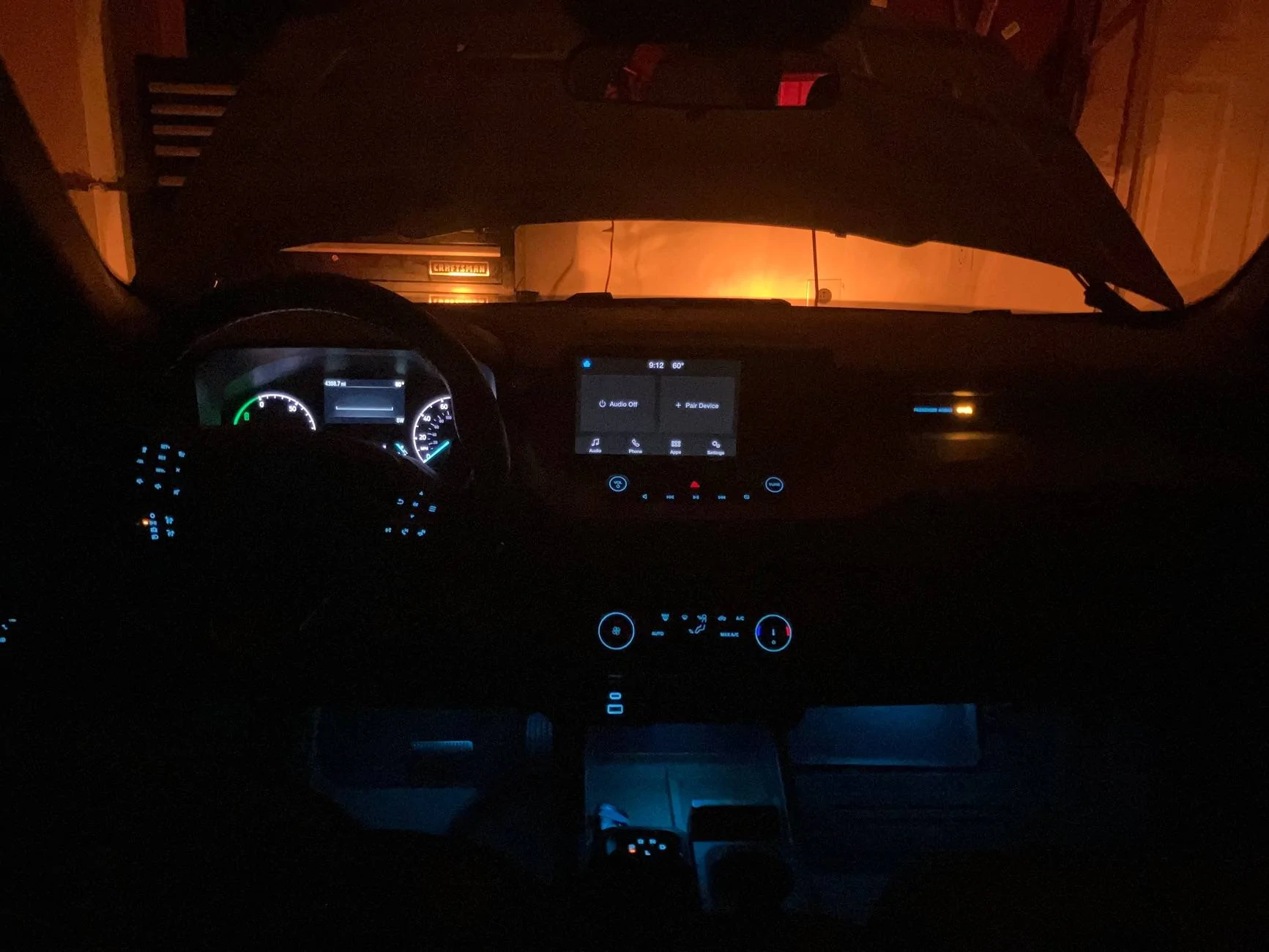
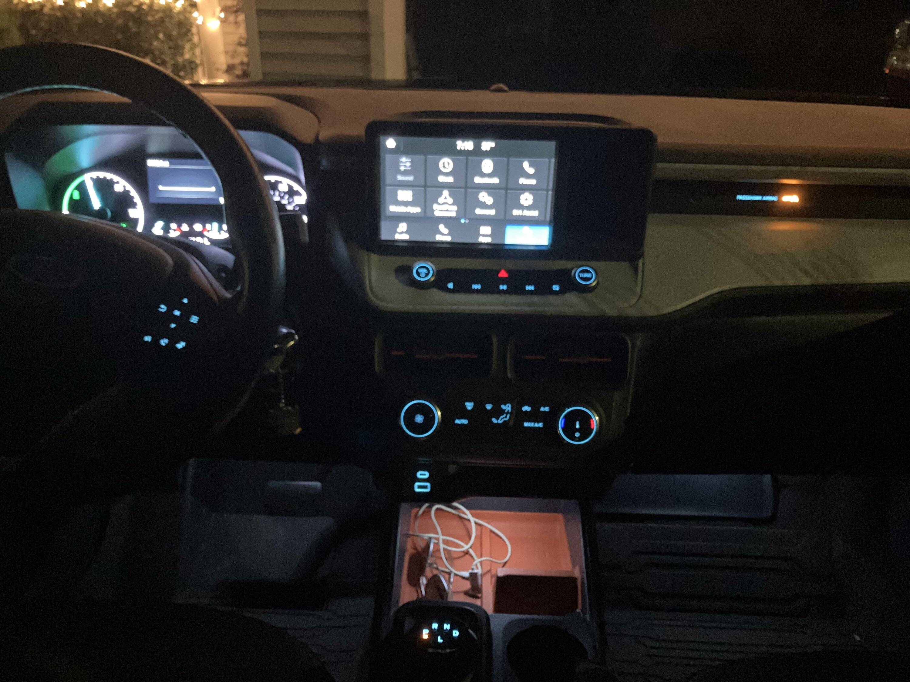
Here is about what they look like, with the center console still being just a hair too bright for my tastes. I took the panel off, cut open a hole, and mounted the LED box inside it for a clean look.
Also many thanks to @GDI Guy who walked me through a lot of the electrical theory in this, I spent many hours researching how LEDs worked, how to wire them, etc.
While doing so I also wanted my ambient lighting to be easily modified, so I created a "power block" out of a permaboard and mounted the resistors (I went with 3.3k to keep light output down a little) to it, and put it in a housing, using JST connectors to wire up each light. This allows them to be replaced/expanded easily and/or replace the board with a potentiometer to adjust brightness when I get around to adding that.
I used "clear" PLA filament when printing, it's not clear but clear enough for light transmittal:
Using a Permaboard breadboard I soldered in JST connectors to allow easy plug-in access for the power (bottom right) and up to five LEDs. After extensive testing in my garage I ended up with 3.3k resistors as I found those offered the best light output levels, with lower resistance making it too bright for my tastes (YMMV). I placed the board in a box I also 3D printed. I'd like to replace the high resistors with a potentiometer or similar in a future version so that I can adjust them to my desired output dynamically.
Testing them with a power supply set to 14.5v shows how they are designed to work, using plug 'n play power so you can just plug in ones as you expand or replace the ones that go bad with another easily. Being LED and using very low output (roughly 3 mAh IIRC) they should last a very long time. I used a fuse tap and tapped into a new circuit to power the box, but they will draw very, very little power combined, about 1/7 of an amp.
Here is about what they look like, with the center console still being just a hair too bright for my tastes. I took the panel off, cut open a hole, and mounted the LED box inside it for a clean look.
Also many thanks to @GDI Guy who walked me through a lot of the electrical theory in this, I spent many hours researching how LEDs worked, how to wire them, etc.
Sponsored
Last edited: